Quarter wavelength impedance matching (1/2)

Вставка
- Опубліковано 8 лип 2024
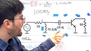
- #176 In this video I continue looking at impedance matching techniques by analyzing a narrowband lossless method that is implemented without using discrete components but rather pieces of transmission line. Now, not just any piece of line will do, but rather a specific length of line is needed - a quarter wavelength of the used frequency.
Related topics:
Resistive matching: • Electronics tutorial -...
Lossless matching part 1: • Lossless Impedance Mat...
Lossless matching part 2: • Lossless Impedance Mat...
Transformer matching part1: • Wideband coupling - Tr...
Transformer matching part2: • Resonant coupling - Tr...
Transformer matching part3: • Coupling experiments -...
Quarter wavelength matching part1: • Quarter wavelength imp...
Quarter wavelength matching part2: • Quarter wavelength imp...
Special Thanks to all my supporters on Patreon! Especially Ralf B., Paul Pr. Richard, Jonathan Alvarado and Tosta!
If you liked this video be sure to check out my other videos and you can also subscribe to be up to date with all the new ones!
If you want to support the creation of more and better videos please consider checking out: / feszelectronics - Наука та технологія


This is one of the best quality electronic channels on You Tube. Thanks.
I totally agree!
Very well explained, and I thank you for the equations and the plots. I look forward to part 2 of this video!
This channel is gold !
I built a stereo 100Mhz 100watt Amplifier to amplify FM radio signal. It requires a total of 4 mini transmission lines between segments in the circuit. If you see a circuit with what looks like a small single loop of coax cable you know that is a part of the circuit that required an impedance match between the points. It was a fun project to build and it worked well. It amplifies the signal to transmit on an antenna. You simply connect an fm transmitter to one end, and on the other the antenna and you have 100watts signal at the antenna. It's a tricky circuit to build properly because each side has to be exactly the same and it really needs to be distortion free since it is the actual FM transmission signal that is both input and output. It's definitely not a beginner project!
I like the SPICE episodes on your channel.
Excellent tutorial, and I mean excellent!
Another impedance matching method using coax (or transmission line), maybe to match impedance of an antenna is the `twelfth Wave transformer`. It uses two lengths of coax to match small impedance differences, say for example match 50 ohm cable to 75 ohm antenna. Details can be found on a google search.
Really interesting! I was researching the stepped impedance matching method that increases bandwidth, but this 12th wave transformer is also interesting because of its simplicity and its bandwidth reduction!
I love how you showed the actual SMD devices! Thanks for this video. 73 de VK2AOE
Muito bom !
Well done Sir.
What type of fountain pen have you got?
Could you do a video about how phantom power works.
Nice one again! Would make a good start for a look at stepped impedance filters too
I actually did think of that, its quite an interesting subject. Maybe next year I will cover that also.
Hi FesZ, I built a retro microprocessor circuit and made PCB's for it after breadboarding. I noticed that on the TTL clock line driving the clock input of the external CMOS 5V 16550 UART chip there was a lot of ringing. Obviously this is due to an an impedance mismatch between the driver and the input. Data sheets tend not to give details on the input/output impedances of devices so other than taking an adhoc approach to fixing a problem after the fact do you know of some mechanism to determine these impedances in digital circuits experimentally before laying out a PCB? That way the design can have the appropriate matching circuit out of the gate, even it's just damping resistors? Thanks for the excellent content! Always look forward to your videos.
I would select an impedance for the traces, let's say 50 ohm and put a series resistance in the output of the driver and try different values until you see cleaner edges. Adapting only the source is good enough in a lot of cases.
You can estimate the output impedance from the VOL and VOH, by dividing this voltage by the current at which it was tested(all found on the datasheet) but this is only an estimation.
@@Gengh13 Thanks!
What frequency? Consider the wavelength involved versus the length of the traces involved and ask whether it can be a transmission line (>> 1/4w) or if it is more likely a lumped element (
I have seen wire antennas matched to 50 Ohms without a matching circuit. Is the 3*wavelength/4 monopole a way to do this?
I guess that "matching" is just highly recommended but not mandatory. However, from whay I found so far, the "ground plane antenna" ( a variation of the basic monopole) can be built to have 50R to begin with, so no matching is really necessary.
Hey make an LCL transformer, that would be an interesting project