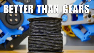
14 degrees of freedom servo arm with capstan power assist

Вставка
- Опубліковано 14 жов 2024
- Inspired in large part by this: • The Perfect Robotic Te...
14 micro servos pull on cables (dyneema fishing line)
Cables wrap around capstan for power assist.
Cables go through PTFE tube to their respective articulated joints.
Joints nearest the tip move easily because they are lightly loaded.
Joints toward the root are under very high strain and move with difficulty.
For high-stress joints, PTFE tubes appear not to be stiff enough and tend to buckle.
Capstan also gets hot rather quickly. I dare not run it for too long or it could fail, and depending how it fails, it could be bad.
More details here: www.thingivers...
I think this may be as far as I take this project, or at least this version of it.
I still like the capstan power assist idea and I have ideas for improving the efficiency. I still think Bowden cables are a good complement for capstan power-assisted cable drives, but for moderate to high forces the housings must be made for purpose, like bicycle brake cables.


Now I can pick up that lost pick in my guitar.
just use this thing as a whole new guitar. It has plenty strings!
Speaking of guitars, my build is partly inspired by this guy: ua-cam.com/video/qihjxvOIFr0/v-deo.html
@@jamiekawabata7101 Oh! I though of Zoolander movie after seeing that. How dirty-minded I am.
@@jamiekawabata7101 can you please upload a video explaining the working of capstan
Inverse kinematics with this should be a nightmare. The capstan is a very neat idea! I love the whole thing, well done!
I can use some technic to avoid that, like fabrik or st like this
@Mustache Merlin Before hooking up the cords I was moving the arm around manually, which I guess is like a physical IK solver. What struck me is how easily I ran into singularities. I think it is related to gimbal lock, but I'm not an expert in such things.
Maybe this is already a solved problem. Either way, I'll leave it to the pros.
@@jamiekawabata7101 If you want to solve without singularities, you need quaternions.
Well , in that case the computation power needed for solving eqn will be hell lot of.
@@jamiekawabata7101 You ARE the pro!
I would ask why does this even exist, then I realized it's awesome and that's justification enough.
So, when the wire wants to pull, it constricts around the capstan/axle, and gets help? Pretty neat!
The practical method would be more fluid servo driving.
I don't understand a bit but ok
@@glitter_fart Does that system relate to a clutch? The servos engage/disengage the conection to a stronger motor that is always running.
@@glitter_fart thnx I have a better hold of it now
thanks this comment thread was really helpful
This is so far the best DIY arm design ive seen on youtube yet. All the others only tension uniformly through the segments while this one actually controls each segment independently.
Thanks! Part of the inspiration for this came from GDFW which had independent control of each segment. I feel that the new element I'm bringing is the capstan amplifier.
That is a very interesting design. Clever use of the capstan. Would be extremely useful to me if the number of degrees of freedom and the amount of lash didn't result in so much variability of the end effector. Still a really cool design.
some engineering shop has ball joints etc you can grip with hydraulics, might make it stiff enough. not sure. lots of sheetmetal layers clamping together for a hinge is very effective. I suppose you could switch on one or more of a few zones for motion at a time.
what if you use a feedback loop to correct the movement instead of hoping that x+1-1=x?
The power assist is really genius. It's very effective, and incredibly simple. Beautiful.
Dude that capstan thing is fantastic. *steals with attribution*
This clearly illustrates that the challenge to creating lifelike androids is not in hardware, but in software. 14 degrees of freedom yet the software is using it like it has only 3. Create a software abstraction layer that calculates or reads through sensors the end point of the arm, positions the end point using that data, and routes the body based on one or more provided routing points. That way you can feed it where you want it to be, and what free space you want the body to be flowing through, yet the abstraction layer software does the heavy lifting to get the controllers to make it happen. Then you can use the API to perform useful functions with this arm and know that it will just work. (Until it doesn't for some edge case, then reiterate the abstraction layer).
This basically use the end servos to clutch onto the driving middle bar to achieve the torque/movement. Neat
Doc oc will be very proud of you
Perfect valentine's gift 🎁!
I can only imagine how long it tooks to run all those lines! Cool capstan idea
Could you imagine what Jim Henson could have done with something like this. Nice work here man !!
C'est très ingénieux de votre part
Interesting ! What is the purpose of the continiously rotating axle between servo and arm, keep a constant tension ?
The rotating rod is a capstan which amplifies the tension from the weak servos so it is strong enough to move the arm. It is like a self-regulating clutch that assists just enough to move the output (arm) side by the amount requested by the input (servo) side.
@@jamiekawabata7101 yeah you see these on sail boats sometimes. You can wrap a rope around it and it really doesn't begin to pull until you put some tension by tugging on the rope. Genius use!
@@IronCrown That's a good question. I don't know. Aramid-like polymers are supposed to be abrasion resistant and heat resistant so it should last longer than say a cotton string.
@@jamiekawabata7101 but capstan amplifies tension only one way, in this case string have to go two ways, thats what I don't understand here.
@@pauliusvaitekunas1943 2 strings for every servo. 1 string wrapped in one direction on the capstan and the 2 string wrapped into the other direction. This results in two way amplification.
To increase the stiffness of the PTFE tube, you can sleeve it in another stiffer material. It doesn't even need to be the exact outer diameter of the PTFE, as long as the space between the inner support tube and the outer PTFE tube is less than the bending radius of the buckling you're observing.
makes whole thing heavier and stiffer to actuate, kinda rocket problem - more fuel takes more fuel to lift, which takes even more
There are also the possibility of using close-wound springs, similar to bicycle brakes but smaller. Joshua Vasquez uses something like that for his tentacle (ua-cam.com/video/_zE-RMDYHGs/v-deo.html) and capstans come into play within the cables as well: hackaday.com/2021/01/26/cable-mechanism-maths-designing-against-the-capstan-equation/
Every thing must be tried, even if the result does not meet expectations.
Really cool but I don’t get what the drill is for? I know that the motors are pulling on the wire but the drill doesn’t make sense.. please explain…I assume that’s what the capstan Power assist is But this is the first time I have ever heard of it and I have been a tinker for a long time…
Its a power assist using friction from the string wrapped around it. whenever a servo "pulls" it tightens the string around the rod, and like a clutch absorbs the power of the rotating rod which then strengthens the pull of the control line. At the same time, the servo is giving the other line some slack so that it does not tighten over the rod and releases the line as it needs to.
@@d7588 i would understand if it were a capstan for individual wire, but there is just one rod for all of them...
@@Guds777 It's a loop attached to every joint. Each direction wounded the opposite direction on the rod. I couldn't figure it out at first as well.
this capstan power assist seems pretty novel to me :o clever engineering
@@tanchienhao Well when it works, it's clever. But the environment must be free of fatty particles ;)
i'm guessing that shaft that's continuously rolling is to make the strings move more easier/friction or something
I think it’s to pull the strings forward because the servo can only pull in one direction
That is the capstan. It multiplies the pulling force of the servos. It also appears to help keep the tendons neat and taut.
Its a force multiplication trick.This is the same trick that is used to pull ropes on large boats. When you pull on the rope this tightens it around the rotating cylinder, this causes a lot more friction on the rope, so the rotating cylinder starts pulling the rope with significantly more force. With this you might pull the rope with 10kg of force while the rotating cylinder adds 100kg of pulling force. Then when you don't want it to pull you simply stop pulling the rope, the rope loosens, friction goes down and it stops pulling it.
Here he is using this trick to multiply the force of the servos. They just tighten the string while the drill provides most of the actual force.
@@berni8k it’s spinning the wrong way for that, it’s just to loosen tension because the servo can only pull not push
@@wayne9005 Looked at the video again and to me it looks like the rod loo is pulling towards the servos. It is rotating counter clockwise and the string comes in at the top, does a loop downwards and leaves the top again towards the servo. I don't see why you would need a force in the other direction, the servos can move in both directions while trying to push a string just makes it sag or crumple up. Notice that there are 28 strings for 14 axies. The reason for doubling up the string is that one string pulls a joint in one direction, other string in the opposite direction, hence no pushing is needed
You're a mad scientist, Jamie.
Gotta admire that systems thinking/organizing to keep track of all of those strings, I think if one went too far, break it/have to rewire
then again, I'm not entirely sure how it works, the roller thing seems to keep going in one direction
This is badass. This deserves wayy more views
So that constant spinning drill shaft gives it a boost in power, okay I get it, took me a minute to understand that part
this is doctor octopuses beginning
I saw a very similar multiple degree of freedom arm done in a research lab in The Chicago area in the 70s using loudspeaker voice coils as the drivers. While it was able to access almost any point in the hemisphere, the project was abandoned because the path of travel was impossible to control. With more modern computers this might now be possible, but still difficult.
Difficult yes. I imagine this is where AI comes in. You know, those learning algorithms.
What purpose does the drill serve?
Are the strings wrapped around that shaft? I'm guessing it's helping to pull the string in
That's a really interesting and innovative idea with the capstan.
Wow really nice use of the capstan. Never seen it done like that,
Great project! Why do you need a rotating shaft across the strings?
Very interesting mechanism, but IMHO the title would be more accurate if it was "14 axis servo arm" as (strictly speaking) there are only 6 DoF existing but as many axis as you want.
I'm being picky here, but nonetheless it's a very cool video and one heck of a clever idea
If you're speaking from a systems/kinematics standpoint then the equations governing this thing's state do have 14 degrees of freedom, even if the end effector only has 6
@@nebnoswel looking at it like this it does make sense !
@@nebnoswel Hi, I didn't quite get how there would be 14 DOFs. Would you please mind explaining? Thanks :)
@Only Yt sure, so basically the end effector (tip) of the arm does have six degrees of freedom, in that it can translate in 3 dimensions and rotate about 3 axes, in other words, it can end up in any point in space (X,Y,Z) and any orientation, denoted by an angle of rotation around the X Y and Z axes. But there are multiple configurations of each of the 14 joints that could result in the same end effector state. As silly as it is, see this gif for an example: media.tenor.com/images/1819da03ee555fc9c76bb24dcbc4dfa2/tenor.gif
So even though the cats head stays in the same position and orientation, it’s back is curving opposite ways. Similarly, the arm could have many different curvatures along its length while maintains the same end condition.
So, the program that controls this thing is basically solving an equation repeatedly at all times. In robotics there’s something called “inverse kinematics” or IK, which is the process of giving the computer an end effector position and orientation and having it back solve to figure out the position of every joint individually in order to achieve the desired end effector state. Since there are 14 joints to be adjusted in order to control the end point, the equation that the computer is solving has 14 variables or degrees of freedom. In some ways this is more complicated for the computer because it means there are multiple (sometimes infinitely many) solutions for a given end. On the other hand, it means that if 1 solution would cause the arm to collide with some obstacle in the environment, it can choose another one that will not, meaning that it in general it is more resilient/more likely to find a valid solution.
Hope this helps!
Doooooof.
I love this piece of engineered robotic arm, I wish I had so many elbows. Good job!
Instead of having one capstan, you could add a capstan for each line. Then have the motor turn on individually depending on which line is under too much load.
That's a very good idea. He says that joints nearest the tip move easily because they are lightly loaded while joints toward the root are under very high strain and move with difficulty. With capstans for each line it could be tuned better for the variance of joints whether nearer the tip or nearer the root.
@@ExtantFrodo2 Where it falls down is that each line will need a position or tension measurement device to turn on the motor in the correct direction. It would probably be easier to use something like pneumatic linear muscles as the length of travel of the line is quite small.
These are good ideas. I think there are two separate problems that are mostly unrelated: one, how to operate the capstan efficiently to minimize heat buildup, and two, how to transmit the tension from the capstan to the joint and operate the joint without running into mechanical issues. The tubes can only tolerate a certain load before they begin to buckle, and for the joints near the base, the loads are high, as ExtantFrodo2 mentioned. But the failure of the tubes does not have much to do with the capstans. The same problem would be present if high-torque servos were used directly. Perhaps the segments near the base could be wider, for more leverage, or perhaps a stronger cable system could be used for some of the joints.
Where multiple capstans could be an improvement is in the area of heat dissipation. The heat dissipated is proportional to the tension of the cable multiplied by the speed of the capstan. The tension of the cable of course relates to the strength of the arm and the speed of the capstan determines the maximum speed of motion, and the axes do not all have the same demands for tension or speed. A single capstan in the current configuration provides each axis with the same amplifier. With multiple capstans, or possibly one capstan with sections of different diameter, the amplifier capabilities could be better suited to the individual joints and perhaps generate less heat while still covering the needed strength and speed.
@@jamiekawabata7101 I remember some very neat designs that used a set of pulleys at the joints to reduce the tension needed. Maybe that would work?
@@matejlieskovsky9625 Yes! This could improve leverage without needing the joint to be wide. I think I saw one on Skyentific
now just put four of these on your back and you've got a great doc ock costume!!!
Very nice work! My compliments on the very nice imlpementation, I love it that you also 3D printed the mounts for the electronics in the same style :-)
I could use the servo drive and capstan amplifier for my own snake-robot arm :-)
For some reason I can feel how painful it should've been to build! :D
Good job!
The cleats where the strings attach to the plastic parts are absolutely essential, at least for me. Without them, if I were tying knots instead, I would have quit with fewer joints.
Neat! The way of amplifying the power is really cool! Keep up the good work!!
Dr Octopus' arms be like lol
Jokes aside, I really liked so much!
Congratulations!
Never seen a capstan used in anything close to this. What inspired this awesome Idea?
I love technology! Look how this super small arduino micro is controlling this giant robot arm
That is darn clever, awesome job.
Coming from an electronics background, that mechanism with the capstan assist somehow reminds me of an emitter follower configuration of a transistor.
This so simple Solution.. wow great job!
That's really clever. Is 14 arbitrary? Or is that the maximum amount you've been able to get to work?
The length of the arm puts higher stress on the joints near the base and the plastic tube is beginning to buckle under these loads. The string and the capstan are plenty strong but the tube is failing in compression. I had designed for 2 more servos (16 total) but a stronger bowden cable system would be needed for at least some of the joints.
So to answer your question 14 is the maximum that I've been able to get to work, and that's why.
@@jamiekawabata7101 that's still crazy impressive, 14 degrees of freedom with high resolution movement is an amazing feat of engineering. I wish you the best of luck in your future development
I like the power assist! Great idea
This is the beginning of the end.
This is how T 101 got started
then he smiled a John
no one is safe now
pandoras box has been opened.
You've Created A Very Accurate ElectricoMechanical Articulated Tail That Can Move Like Any Other Animal's " Tail " Works !!! Great Job !!! Now You Need To Add Emotions Sensitive Receiving Pads&Micro-ElectroMechanicalize The Servo's !!! Then Add Any Animal Fir Or Scales On It For The Desire Of The Buyer's Desire !!! Then You've Got A Product For The People Who Dress Up As Any Animal That Have Tails !!!
This is inspirational!
I have some smooth, thick-wall stainless tubing, 8mm O.D. I think, with a 3mm bore.
If I water-cool the tube through the bore (ignoring typical problems with rotating fluid seals for now), I wonder if the capstan would stay cool enough?
Failing that, perhaps short stacks of thin copper washers with spacers, in tight contact with the shaft, on either side of each winding, forming a heat sink/radiator to dissipate the heat?
I would think that would work. And with an 8mm OD it would be relatively easy to support it mid-span if you wanted to. I believe capstans work equally well (or perhaps better) with larger diameters, so there could be many choices for tube, but as you mentioned, pumping coolant through while spinning requires some care.
@@jamiekawabata7101 Thank you! I just think the capstan is a brilliant idea.
Very interesting. You just need to create a joystick to control the movements and make a video taking something and putting it somewhere else.
I liked the creative idea to keep the strands taut.
So the future demo is here!.
Capstan's have a vertical shaft. This is more like a horizontal shaft windlass.
Why don't you extend the cables from the servo and put a weight at the end hanging from the table? Or a spring. You can then tune the weights depending on the position of the cable in the arm. It would put a load on the servo but they probably are already loaded to a high degree.
Nice project i like it but can you please explain to me the purpose of the drill and what's gonna happen if the drill stop spinning?
Thank you!
That is the "capstan power assist" in the title and in the description where it explains the setup a bit. It tasks a lot of load off the servos allowing them to be as small as they are, basically.
You could program it to be able to move multiple sections at once that would be sick and then you can use vr to control it
Criação dos tentáculos robóticos de Dr. OCTOPUS
I am wondering why that shaft is rotating
I see you're one step closer to becoming Dr. Octopus
Wow. Thank you for sharing this project with me! Excellent work! :-) Love the description too.
What is that rotating thing in the middle good for? Tension?
It the rotating shaft serves as a capstan, which amplifies the low tension from the servos into higher tension needed to drive the arm joints. The friction of the cord on the rod causes it to apply extra tension on the output (arm) side, but if it pulls too much, the cable loosens on the rod and the friction decreases. In this way it achieves a balance, pulling just hard enough to match the displacement of the servos. If wrapped multiple times, the output tension can be much, much higher than the input tension (en.wikipedia.org/wiki/Capstan_equation), while at the same time the output displacement follows the input displacement very closely. (Posted by OP somewhere below)
@@izybit thank you very much!
Thank you for the question and the answer
Using a few pieces of spaghetti and a couple pieces of yarn I made effectively the same thing, but it also had a neat function of making my 7th grade teacher scream her lungs out and run out the room.
This is basically a spinal chord...from an aesthetic standpoint....but if your nerves were muscles.
So Doctor octopus had a always a truck behind him full of servo's ?
Now the airport body check will get a little bit more interesting.........
I dont get it, what does the central axis accomplish by turning?
The servos here are always pulling, never pushing; and they might run out of torque. The axis is a capstan and it transmits a little extra force to the wire in direction of servo pull, so the servos need less torque. I can't really tell whether it's any effective though.
Pretty neat, but it looks like you need some stronger servos as you move down the line. The top is very responsive and quick, but about half way through, it really starts to struggle.
It's true the joints near the root have larger and larger loads, and it struggles. The servo (with capstan amplifier) is plenty strong enough but the plastic tube is not strong enough and it buckles under compression.
What is the spinning shaft for. Provide some additional force advantage to the servos using friction?
I wondered this too
Is that rorating rod in the middle merely for tension or is there another reason? Very cool contraption :)
Very cool, you have a very interesting channel! Keep up the good work and the cool projects! Subscribed.
This is awesome! It has almost all of the information I need to have the servos for my animatronic bird be remote from the bird itself. :D What size PTFE tubing and what weight of cabling did you use? how do I know which ones to buy?
I used PTFE tubing from Amazon with 1mm ID and 2mm OD. For the cable I used braided fishing line with Dyneema, which is similar to Kevlar and is extremely low stretch. Also strong, but minimum stretch is what's important. Most fishing line is nylon and will stretch a ton and it will be awful. Look up the low-stretch variety (there are several). I think the line was 50lb test. The PTFE tube is the weak link and it tends to buckle under modest load.
All control wire control by servo motor but what is the function of continuous running shaft with hand drill machine
Reply?
I feel like this is how a robot arm would have worked in the 1970s, and it would have a computer the size of my living room to tell it what to do.
'For those hard to reach places'
@Jamie Kawabata can you upload a video explaining working of capstan.
Perfect tail for a Boston Dynamic Robot Dog
I had thought about using this kind of mechanism in a tail, i don't know how i would hide a bunch servos on someones body though.
Very nice!! I want to see you turn off the drill and turn it back on. Shows off and being turned on.
I have this exact same tile in my work area/basement. Does it matter which direction the capstan applies torque in? Or should it always be towards the driving/motor side? Also, did you just use a standard 8mm rod, like the kind used with LM8UU bearings? I have a fast IK solver which I want to try to use with something like this. 14-DOF might be overkill for me though.
Can somebody explain what the powerdrill and rod with wires wrapped around it once.
Great job.
Could you tell what is purpose of rotating shaft with coiled strings around it ?
It the rotating shaft serves as a capstan, which amplifies the low tension from the servos into higher tension needed to drive the arm joints. The friction of the cord on the rod causes it to apply extra tension on the output (arm) side, but if it pulls too much, the cable loosens on the rod and the friction decreases. In this way it achieves a balance, pulling just hard enough to match the displacement of the servos. If wrapped multiple times, the output tension can be much, much higher than the input tension (en.wikipedia.org/wiki/Capstan_equation), while at the same time the output displacement follows the input displacement very closely.
@@jamiekawabata7101 fascinating
@Nani Nano dont be, I also didn‘t know that😊. My guess was that it somehow tensions the strings but that was about it.
@Nani Nano Too young to have played an audio cassette? :) I'm jealous!
very cool prototype
Dang I was really wanting to see some fancy movement
Yeah. Should always try feeding in some sine waves of different frequencies on sets of joints or something. Just for the dancing at the end of videos.
Hello there!!!
Awesome!!!!!
Can u share how to make this
Oh look is a 14 degrees of freedom servo arm with capstan power assist
It comes supercharged also
Oh mighty Shai-hulud
Keeper of balance
Bless the Maker and His water
Bless the coming and going of Him
May His passage cleanse the world.
Nice technology but what it does?
Fabi aye alla irrabiki kumma tukazibban....
Like tendent in our arms.
why do you need the graphite tension rod to be turning?
awesome I need something to hold my soda when I'm walking
Don’t the tie rods consume along all that constant friction the assist shaft is producing?
I don't understand how the capstan power assist work, through friction? the cables wrap around the rod and slip, how friction could help? Can someone explain? Thank you!
My title: i build a mechanical snake
Absolutely crazy!
ok I gotta know, how does the power drill thing in the middle help this in any way shape or form. It seems kind of counterproductive.
very nice but you should make electronic muscle system by using H and A band in real human muscles system (when make EMS can use selenoid )
This is so friggin cool
Interesting power assist. I wonder how long can it run for before the line around the capstan wears out?
Do they make these with a soft silicone cover for uhhh reasons?
Can it determine the most efficient way to move?
What is the part in the middle for? Surely that will just wear out the cables?