
Вставка
- Опубліковано 1 гру 2024
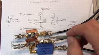
- This video shows how a mixer can be used to upconvert the HF frequency band into a higher frequency IF (intermediate frequency) so that the RTL-SDR can be used to receive/listen. A homemade double-balanced diode ring mixer is shown here, but something like the inexpensive ADE-1 from Mini Circuits would work very well also. Higher performance operation (less interference, intermodulation distortion, etc.) can be achieved by utilizing pre-selection filtering in the RF path, and IF (intermediate frequency) bandpass filtering between the mixer IF output and RTL-SDR input. The controls to automatically remove the IF offset from the display, and to control the RTL-SDR tuner and demodulator gain from within HDSDR is also shown. Some 40m SSB/LSB signals, and some AM shortwave broadcast signals are listened to as examples. Here are a few relevant links:
Video on basics of mixers and frequency translation:
• #83: Basics of RF Mixe...
Basics of a diode ring mixer:
• #167: How a Diode Ring...
Measurements made on the preselection and IF bandpass filters in an HF upconverter:
• #175: Filter functions...
Ham It Up Upconverter by Opendous, available from NooElec:
code.google.co...
Upconverter by CT1FFU:
www.ct1ffu.com/...
There is also an NE602 based upconverter featured in the January 2013 issue of QST magazine.
Here's a nice summary of 18 upconverters in a blog by KF7LZE in Sept 2014:
blog.kf7lze.net...
Notes from the video are here:
www.qsl.net/w/w...


These videos are gold.
couldn't agree more, as a senior ECE who is stuck at home given everything. I am FASCINATED. Love the content sooo mcuh
Very interesting! Your videos are amazing!
I just heard about SDRs and this accidentaly sparked my interest in analog electronics too! The analog electronics stuff has been a scare for me for a long time as a new generation MCU hobbyist, but this video really showed the application of basic mixers that I can start learning. I have to watch you mixer tutorial now!
Thanks!
I have honestly learned so much from your videos in the short few months I have been watching.....its almost like taking an extremely accelerated and focused course on RF and electronics. Just wanted to say thank you Alan. Your channel is so much appreciated.
73's buddy - N0BPS
I'm very happy to hear that you're enjoying the videos so much.
I clicked Thumbs up quickly, A. Clear Audio, B. Good video. C. The schematic explanation blew me away to your intended end use. Your filtering explanation and why and where they would be necessary was key to me. I clicked subscribe because of your comfort level of the math involved. I enjoyed this video. Also I appreciate your Non rush approach to explains things on the note pad. Thanks. I am extremely new to the knowledge of SDR technology as of only 1 week ago... today being 12 Jan.2018.. to bump into this video caught my eyes and ears. KF2ms Biddeford,Maine
I hope you like my other videos just as much!
Lee Fuller - This is one of the best electronics channels on UA-cam. I’ve been an EE for 39 years (mostly RF and analog, with some digital mixed in) and I can say for certain that Alan (W2AEW) presents these topics in a clear and concise fashion, which makes the subject matter much easier to digest, especially for novice electronics enthusiasts. Teaching these subjects, and making them interesting and educational, isn’t an easy thing to do. Even after all of my years as an engineer, I still learn or re-learn a few things from him. Many times, I’ve seen electronics students make comments on here such as “I struggled with that in school and you made it easy for me to understand.” He has TONS of great SDR, electronics and Ham Radio content on here. Welcome to SDR! 73’s
your topics are always amazing
Love your videos, big help in understanding how a radio works. Now, I am playing with old tube radios, mainly Heathkit. I have a receiver, an HR10B that I was listening to one evening, and the signal just faded away into nothing, no static, hum, or anything, just all of a sudden, nothing coming out of the speaker. I've been told to look at it with a scope, mine happens to be a Heathkit also, and it works very good. Now I'm told I can trace the signal coming in from the antenna through the different tubes from grid to plate and watch it on the scope as it's amplified into a signal that the speaker can recognize and this way, by following the path, I can find the area in the receiver where it stops, and then I will know the components to check in fixing it. Now that all sounds pretty easy, but if you don't know what you are looking for on the scope, it's means nothing to me. I've watched numerous videos on building a signal probe, sounds easy, and it seems like a good idea if I'm looking for the signal, to use a tracer, but that's as far as the videos go, showing you how to build it. I would love for you to do a video of a receiver that has stopped receiving and how to find the problem. I have two right now that happened the exact same way. Any help would be much appreciated, 73 de WA1YDK
This video might be helpful. Please pardon the background noise - the mic was poorly placed when this video was recorded.
Awesome demo... I didn't know that such USB device even exist.
Thank you Mr. Wolke for another great video! If I may: for folks that are on linux and looking for the app - I recommend GQRX for RTL devices. To decode digital signals from analog of GQRX use DSD (digital speech decoder) + padsp to pass it to the PC's audio device for listening.
Thanks again, another great video with great info. As you know, I added filtering to my setup and it really came to life since I live by some nearby transmitters. When using the mixer on HF bands I run my gain around -5db or so in sharp sdr program and when not using the mixer up on vhf/uhf I can run it with much more gain. Even running low gain in the program I sometimes can see overload problems from strong SW stations on hf yet but it is under control.
Thanks again for great clip.
Something, that I learned, which is useful for my professional designs, is to filter LO. It makes sense. Normally, we go to great extend to reduce phase noise of LO, such as current injection coupled oscillators under PLL control designs. However, I never thought of filtering LO, which should have been obvious.
You may try direct conversion with this setup, see how does it work.
Thanks again.
Excellent post. As always its very didactic explanation.
Some considerations:
Try directly extract IF your radio and inject in sdr-dongle.
Trough of a software called OMNIRIG you can go the other way, ie, changing the radio by tuning your own HDSDR and transmit by pressing the PTT.
The use of SDR in ham radio is a very good tool for learning.
Congratulations.
73
PU2SRZ
I have to admit that SDR offers so many advantages over more conventional receivers, especially compared to the old boat anchors that I'm so fond of, but it's hard to let go of the joy of finding a signal as you tune up and down the band, then zero beating your transmitter to his frequency, etc.. But, I do love learning new ways to do things. How much electronics has changed!
I agree. I still love listening to signals on my old Drake 2B or Yaesu FRG-7. I don't use one of the SDR dongles shown in this video - I gave it to a local ham friend. If I want to scan the bands with an SDR, I use one of the many online SDRs.
That was very convincing. I can see my old Kenwood and Yaesu gear going into storage.
I wouldn't go that far - these little RTL-SDR dongles have very poor front end filtering and are easily overloaded...
This is so simple yet awesome. Now I want to build a diode-ring.
Very nice! Gotta love SDR!
I really enjoyed this video thank you making it
Thank you very much for the video and your time.
So a Quadrature Decoder mixes a Local Oscillator and Phase shifter, to yield Real (I) and Complex (90 deg shifted).. is the only reason to do this so that the software knows how to separate what was originally on the upper band vs the lower band? i.e. It has nothing to do with Nyquist?
Would it be possible to make a colpitts that is fm modulated running at say 1mhz (something more stable) with varactor modulation, and then upconvert it with a mixer to hit the 2 meter band? For 2 meter FM? I was worried it might do some strange FM inversion..or it may be difficult to keep the local oscillator out of the output..it would be similar to what you are doing here but used to generate the actual transmit signal. I thought maybe it would be easier to build a stable oscilator at a lower frequency and also easier ro modulate possibly. Just a thought experiment really
Yes, this is certainly possible. In fact, it is similar to how most transceivers operate. The modulation is typically done at some lower IF frequency and then it is converted up to the output frequency. By doing this, all of the modulation is always done at a known, fixed frequency - then, the output frequency is just a function of the LO to the mixer. A filter on the output is used to reject any LO or IF components in the mixer output.
@@w2aew interesting..but the part i am not sure about yet is if the LO has to run say at 144 Mhz, and the FM is coming in from the input at 1Mhz you would get 145Mhz with the sum, correct? I dont see how you could filter the 144Mhz at all in that situation, its too close. So maybe 1Mhz is just low, not enough difference. Either that or the mixer would have to be very balanced with great LO rejection. I am not sure how to solve this. I tried to google it before "2 meter upconversion" but didnt find anything. In fact the difference freq would only be 1mhz below, and prob inverted, thats what i think would cause a problem.
@@researchandbuild1751 This is one reason why there is often a double conversion. Also, the mixers used are often double-balanced mixers (DBM). When properly designed, the LO is attenuated greatly at the output, so you only have to worry about filtering the opposite image.
@@w2aew ok those are good tips thank you. I guess one could make the input run at 15Mhz or so, that way its probably more possible to filter at the LO and up (highpass) basically calculate what band range you want and have both frequencies at a decent division to make filtering more effective. So 145Mhz with 15Mhz would be a 130Mhz LO and you could probably make a decent filter to cutoff 130 but allow 145 and up for example. Im sure there are some more tricks to it but thats the basic idea i guess. Thank you for your responses!
Why is my homebrew downconverter for sdr not working? I am using a diode ring mixer with 10 turns for each transformer and I am using 1N419 diodes. When I adjust my function generator, It does not affect the spectrum at all.
Transformer performance also depends on the core material.
w2aew thanks
Hi sir, great explanation, I have one question, is it the RF input from the antenna we must connect it to the IF input of the frequency mixer?
I know this is going to get complicated so why not start of with a 74AC74 configured as a Johnson counter which drives a PI5V331 configured as a balanced QSD which drives 2x MC1350 preamp chips one for each output where the single ended outputs I.E. I/Q drive a RF Phasing combiner for 455khz so your LO=((VFO+455000)*4) and should remove and birdies that happen during the down conversion process, will this work?
Hi
In some uwb radar systems there are antennas at some frequency like 100mhz 200mhz and other
But how an 200mhz antenna has been used for an uwb signal??
Because there is no any continuously signal there is just some pulses with fast rise and low pulse width (ps to ns) with a repetitive of 10 to 100khz
For example if ihave a signal with
1ns rise time
4ns pulse width
50khz repetitive frequency
What is the frequency that my antenna( for example dipole) have to be set with a nanovna????
The antenna would be tuned for the RF frequency used during the pulse ON time.
@@w2aewactually there is no rf signal like sine wave in the( on )time of pulse there is just some nanosecond pulse that coming out of an avalanche transistor circuit- for example 300v 5ns pulse comes to 1 arm of dipole and -300v 5ns pulse comes to another arm of dipole at the same time with a repetitive time of 50khz so if the pulsewidth is 5ns
Have I use an antenna that tuned for 500mhz???
Or for 1ns use 1GHz antenna???
@@Musicroombar I would think a 100MHz fundamental would be correct (5ns pulse width is half of a 10ns period, which is 100MHz). The antenna would then work on the harmonics (of which there will be many).
@@w2aew thanks 👍 alot
I didn't tested yet antenna designing for such pulses I have to test it
I hope to do not damage my measurement devices :) cause they are high voltage pulses 600v to 1.5kv
Completely unrelated to this video,was wondering if you considered, a series of videos on oscillator types,common reasons for why they don't work even if they simulate fine.. I have had issues with a lot of different oscillator types and apart from a fm transmitter circuit all refuse to oscillate above 28 MHz .
Considering the LO and Fif are in the correct range, may I use ZX05-1L-S+ mixer ( mixer you recommend) to make this project? www.minicircuits.com/WebStore/dashboard.html?model=ZX05-1L-S%2B
Sure, that will work. Plus, it only needs +3dBm LO drive power too.
Neat device. It looks like you could make it into a cheap spectrum analyzer.
I would love to get into shortwave listening, and this looks like a great way in. However, what always stops me is the aerial required, i,e. 20m, 30m, cable strung between trees etc. I just can't do this where I live. Any chance of doing something on small booster type aerials that anyone can build for use in a built up area, it would be much appreciated.
You can often get creative, running wire around the ceiling or in an attic. Or magnetic loop type resonant antennas can work very well in a lited space.
Thanks for sharing, very useful! Do you think a ready made crystal-oscillator (4 pin version) would do the job as LO? I guess this kind as oscillator has a square wave output and not a sine wave... Did you match the diodes for your mixer? vy 73's de gabriel-db5ag
For a diode ring mixer, a square-wave LO will generally do a good job. You will want to apply appropriate filtering to the input and output to minimize aliasing and distortion.
Good to know, thank you.
What is the amplitude of the LO you are generating? would like to try doing this with a home made mixer as well.
I was using +7dBm (500mVrms, 1.414Vpp).
Excellent Allen. What would be your go to active component for the LO of this converter if you were to build one..? I know you were using your sig gen for this one. Also, were you using the small antenna for the dongle or your main mast antenna in this video..? Thanks so much for sharing!
Probably something like a decent oscillator from Vectron or something like that. I was using my 135' dipole.
I'll check Vectron out for sure. Yea, I just knew that reception was a bit to good. I look forward to more concerning this amazing piece of equipment. Thanks again!
thanks for your videos. i'm 'new' to RF and really want to understand and design my own circuits. i'm planing to use a mixer chip on my first build (SA612) and from what i learnt so far impedance matching is terribly important. i want to measure the output complex impedance of the mixer at my frequency on interest (40m band)... i think i know how to measure the input impedance.. but just wonder if you have advice on measuring the output, and if indeed this is commonly done by ham enthusiasts..
thank you so much for your channel, i really get a lot of value out of it.
i have a couple of questions that maybe you could find the time to answer... i am wanting to align an old tube radio but i do not have a signal generator. i do have a function generator, and a frequency counter. i have seen videos showing the IF alignment done with no modulation on the IF (455kHz), where you use only a meter (or scope) to find peak, without need for a tone. but i am unsure if this is possible for doing the RF alignment or if i NEED a tone on that signal. if i do not need the modulation or tone, then i am mostly fine, but if i do need the modulation, could i get that using a diode ring mixer like the one you have demonstrated? i THINK i could run it with LO of say 400Hz, an RF of say 1000kHz and i would end up with something like DSB-SC (dual sideband suppressed carrier) 1MHz suppressed carrier with 400Hz modulation -- is that right? then, if i ALSO split the signal from the function generator before sending it to the mixer, and reinjected that signal back into the line after the mixer, i might be able to put the carrier wave onto the line as well.... would any of this work or am i crazy?
thanks so much for any help, if you can find the time!
It would be better if you have some tone or other modulation on the signal, that way your signal will occupy more BW and you'll better be able to center the response in the IF filters. If you use a mixer, you can add a little DC offset to the LO signal to retain some carrier.
@@w2aew perfect! thank you very much!
@@w2aew does this hold true for RF alignment as well, or only IF? COULD i succeed (albeit poorly perhaps) with no tone doing RF align, or would that just not work?
@@proctormacbelle4904 It depends on what kind of circuits you're aligning. Sure, they can be done with an unmodulated RF signal, but a more precise result would likely be obtained when a modulated signal is used when called for.
@@w2aew thank you again! this inspires me to experiment.
Thank you
You must have a good antenna to get so many shortwave stations.
Would it be possible to make a diode ring mixer without the coils? (I hate making coils :) )
You may want to look into using a Gilbert Cell mixer
@@w2aew Thanks, today i remembered that i have some tiny transformers that have tapped secondary, would it be possible to use those? Or does it need a specific number of turns?
Excellent!!!! Thanks
This is such a tempting project. Could you pls tell us if you have an LNA at the antenna? Do you have any points we should keep in mind when doing this experiment that you forgot to mention in the video?
Again. This is such a wonderful video. Such simplicity.
No LNA was used. Note that the conversion loss will likely be about 6dB, but that's not usually a problem. Without filtering, it is possible to to get images, but you can work around that too in most cases.
Do you recall what antenna setup you had at this time?
I was using my 130 foot long wire dipole antenna that is up about 30 feet.
Would it be that hard to use a mixer to listen to shortwave on a regular am radio?
No, that wouldn't be hard to do.
Τhanks, are you suggesting a year arrl handbook to choose it?
Another great video! I suppose once you've done this enough the wonder starts to fade, but the whole concept of mixing frequencies is such a cool application of physics I think I would still have a little bit of joy seeing these signals translated so cleanly up the spectrum.
Quick question...can the diode ring mixer be used to downconvert as well? (I'm assuming that would be the 'difference of two frequencies' you mention at ~1:30) I'm interested in downconverting ultrasonic audio that's in the range of hearing for animals (domesticated in particular). Basically ultrasonic mic -> amp (?) -> mixer -> amp (?) ->headphones/ADC
Yes, absolutely. This is what is done in most broadcast receivers. In the US, FM broadcast is typically downconverted to a 10.7MHz IF. AM broadcast is often downconverted to a 455kHz IF.
Nice proof of concept demo. Your channel is loaded with lots of useful info. Tnx for sharing it. 73 OM. KR6K
Thanks again for this video,a question:
are you using arrl handbook very often as a quide to build those projects?
Kostas - Greece.
Sometimes, yes. I use the handbook as well as many other references.
What order filter would be acceptable on the antenna input?
Thanks.
can we use this to make a metal detector
Hey Alan, enjoying your videos and please keep doing what you're doing. You did mention you picked your IF so it was above the FM band but I'm not sure if you're aware civil aviation uses the 108-140ish range. Is this an issue at all?
Not really an issue. My main concern was getting interference from strong FM broadcast stations. The civil aviation signals are not likely to be strong enough to interfere with the up converted HF signals.
Reposted comment:
Is the I/Q technology the same one governments use to record the whole RF spectrum for easy playback at a later date? I've heard there are satellites that record the whole RF spectrum and can relay the data down to the ground, so they can actually "rewind" time and listen to any RF from any source on the planet. I guess they use an array of different antennas in different orientations (phased array) to be able to derive the rough locations of the signals.
_EDIT: Here's the kind of thing I'm talking about:_ X-COM Systems/Tektronix RF Capture and Playback Solution
_EDIT2: I think comment responses should work now._
Yes, the XCOM/Tektronix solution records seamless IQ data over a 165MHz BW. The resulting data can be captured, analyzed and replayed at any time - thus any signal within that capture BW can be replayed as well.
***** Thanks. I wouldn't have thought it to be possible until I saw your first I/Q video. The way you explain it makes so much more sense than other videos out there.
Nice video, tnx !
Did you by chance have time to measure the sensitivity of the current setup ?
73 N8AUM
I'll probably do some of those tests when I play with some of the other upconverters that are properly filtered.
is spectral inversion related to image frequency?
not really. an image frequency is an input signal that is equidistant from the LO frequency as the desired input frequency, but on the opposite side. As such, an image of this signal will appear in the IF at the same frequency as the desired signal (but its spectrum will be inverted from the desired signal).
First of all w2aew, one of my favorite channels on youtube, thanks for all the great content. I bought one of these same nooelec SDRs on amazon when I saw your last video. (I also bought the Ham It Up 1.2 from them as well). Are you using the stock antenna? I have to use all 49.6 dB of RF Gain available in SDR# to get even some of the wFM stations. Is this the kind of performance you see with the stock antenna or your device? Did you have to adjust the Frequency correction? Not sure if I got a bad apple, and should contact the manufacturer. Thanks in advance.
The stock antenna is not very good at all, you'll definitely want to use a better antenna for FM and VHF/UHF and above. For HF, I was using my 130 foot dipole antenna. You'll definitely need an antenna suitable for HF to get enough signal strength for shortwave reception.
Thanks
the mixer should be flipped for upconversion.
since you are shifting up, i'd put the R side to the sdr radio
The RF and IF ports of a double-balance diode ring mixer are generally interchangable, whether you're doing up or down conversion, or using high-side or low-side injection.
@@w2aew most datasheets I read on mixers show a lower frequency response for the I port, and if it didn't matter why would they bother to mark the ports of the mixer? I have designed many rf circuits, your mixer is reversed.
Could you down-convert twice to avoid spectrum inversion?
If you tune to the sum mixing product (f_lo + f_hf), there won't be any spectral inversion.
+w2aew I am considering options for downconverting from 2.4GHz and possibly 5.8GHz whilst avoiding spectrum inversion. Case D shown on this website is interesting. As they present it, if the IF is negative the spectrum is mirrored at 0Hz resulting to second inversion. So theoretically it should be possible to maintain the original spectrum downconverting this way.
www.rfcafe.com/references/electrical/spectral-inv.htm
If you want to downconvert with one conversion and no inversion, then simple use low side injection (like A/B).
+w2aew Doh! Of course, I was fixated on something else and failed to see the obvious. Thank you very much for answering my questions.
What is low side injection?
my local ocilator is around 100 mhz no problem at al with de broadcast fm band
Amazing little device. Why win xp? Because of drivers?
XP since that's an older laptop, about 6-7 years old. I also ran it in the previous video on my desktop PC on win7
Nice
wow , that way you made cheap things even cheaper because of its Extreme capabilities
I love your videos. I hope your Channel is monetized and you are making money off of this. Keep up the great work. Any chance you have the ability and resources to work with cool applications over 20GHz or higher? It would be neat to see you do cooler high frequency videos.
+Eric Gouveia I am monetized and basically make some pocket change with the little ads that pop up during the video. Of course, if someone clicks on those ads, I make a lot more. I don't really have the equipment for 20GHz applications at this time.
EEVblog2 showing an SDR rf front-end circuit in Silicon Chip
magazine: ua-cam.com/video/adSk6suM29E/v-deo.htmlm47s
can you use a 120MHz square wave as the input to your LO?
It depends on the particular mixer, but in general, yes, especially for low power mixers.