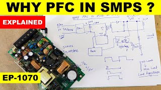
Power Factor Correction | Active Power Factor Correction | PFC Control | Boost PFC

Вставка
- Опубліковано 28 лип 2024
- #PassivePowerFactor #PoweFactorCorrection #PowerElectronics
In this video we will see:
0:00 INDEX
0:27 What us a Power Supply made of
01:18 Limitations of a Power Supply
02:38 Classification of Electronic Loads
02:48 Class A load
03:00 Class B load
03:10 Class C load
03:20 Class D load
03:58 Power Factor Correction Method
04:24 Passive PFC
04:37 Disadvantages of Passive PFC
06:01 Active PFC
06:17 Construction of Boost PFC
07:14 Boost PFC control
09:20 CCM control
10:04 DCM Control
More Videos:
Power Electronics:
Power Factor - • What is Power Factor |...
Powe Supplies:
Full Bridge Converter - • How does a Full Bridge...
Half Bridge Converter - • How does a Half Bridge...
Zeta Converter - • How does a Zeta conver...
Cuk Converter - • How does a Cuk convert...
Buck-boost converter - • How does a Buck Boost ...
Double Ended Forward converter - • Double Ended Forward C...
Active Clamp Forward Converter - • Active Clamp Forward C...
Forward Converter - • How does a Forward con...
SEPIC converter part 2 - • SEPIC converter design...
SEPIC converter part 1 - • SEPIC converter design...
Flyback converter part 2 - • Flyback converter desi...
Flyback converter part 1 - • Flyback converter desi...
Push-pull converter part 2 - • How to design a Push p...
Push-pull converter part 1 - • How to design a Push p...
Boost converter design - • How to design a Boost ...
Buck converter design - • How to design a Buck C...
SMPS basics - • Basics of Switch Mode ...
Electric Vehicles:
Battery management system 2 : • How does a BMS (Batter...
Battery management system 1 : • What is a Battery Mana...
Battery basics part 4 : • Electric Vehicle batte...
Battery basics part 3 : • What are the types of ...
Battery basics part 2 : • What is SOC, SOH, SOP,...
Battery basics part 1 : • Which Battery is used ...
EV motor controllers part 2: • Motor Controllers in E...
EV motor controllers part 1: • Motor Controllers in E...
Charging of EVs: • Working of Electric Ve...
EV basics: • How does an Electric V...
EV parameters: • What is inside the Ele...
EV Motors: • Motors used in electri...
---------------------------------------------------------------------------
Check us out!
Facebook - / foolishengineer-407598...
Instagram - / foolish_engineer
Subscribe now for more videos like this!
Attributes:
Transformer, Capacitor, Inductor, Transistor, Diode - a href="www.freepik.com/free-photos-v..."Card vector created by macrovector - www.freepik.com/a
Fan, TV, Mixer, Electric pole, Oven, Fridge, PC - a href='www.freepik.com/free-photos-v... vector created by macrovector - www.freepik.com/a
Power Supply - Copyright: a href='www.stockunlimited.com'Image by StockUnlimited/a
Lights1 - a href='pngtree.com/so/c4d'c4d png from pngtree.com/a
Lights2 - a href='pngtree.com/so/street-lamp'st... png from pngtree.com/a - Наука та технологія


I dont understand how all of our teachers can be so bad at explaining this stuff. It makes perfect sense if explained well.. i wish this guy was our teacher :) great video!
Thank you so much for watching!! Please don't forget to subscribe to our channel
It's often because the teachers don't really understand it themselves.
There is a scarcity of passionate teachers who understand the concepts. Most of our teachers work to pay bills and they don't know to do anything else.
👎👎👎👎👎👎👎👎👎👎👎👎👎👎👎👎👎👎👎👎👎👎👎👎👎👎👎👎👎👎!!!!🤣🤣🤣🤣🤣🤣🤣🤣🤣
that is INDIAN education system,,,, welcome
OMG! It gets more and more sophisticated after the capacitor dropper circuit!
I thought we could DIY a simple power supply which has power factor of near to 1.
Thank you so much for watching!!
Thank you for this educational explanation and Bravo for the quality of the animations. In fact, I subscribe to your channel. Happy New Year .
Thank you so much, this means alot to me
I just appreciate your efforts 🙏...great explanation
Thank you so much, Glad you liked it!!
Very ingenious. Needs to go more and more .
Sure!! Thank you so much for your feedback!
My experience with inductors is that they're more efficient, in continuous conduction mode. It seems that the Eddy losses in the inductor core are much higher in critical conduction mode, because the lower effective switching speed allows deeper penetration of magnetic flux into the core. At higher frequencies, the skin effect reduces the conductive cross section, reducing overall core loss, despite a possible increase in hysteresis loss.
Tq annayya (Brother)❤....
I'm going to have to watch this again a few more times. It was explained extremely well, but I still got lost about 3 minutes near the end of the video. I'm thinking I might slow down the speed 0.75 and absorb what I missed. Thank you sincerely sir. You are a very very good teacher, that's why in the end I'm confident I will understand 😊
Glad it was helpful!
Love it, thanks!
Glad you liked it, thank you so much for watching
Thank you for the wonderful educational videos
Glad you like them!
Well done sir, great.
Thank you so much
Thanks for an excellent and clear explanation....
Thank you so much for watching!! Please don't forget to subscribe to our channel
Wow.This is so cool....Thanks man
Glad you like it!
Thank you for this interesting explanation.
Just I find that the mosfet is kind of short circuiting the bridge rectified output.
Isn't it?
Thank you very much for the well explained and easily digestible lectures. May I ask you what kind of software do you use for making those slick waveforms in the video?
Thank you so much for watching!! Please don't forget to subscribe to our channel
after effects
I love this channel! Great presentations must take enormous effort to produce.
Thank you very much!
Really nice need more and more videos electrical related 😉
Working on it!
Thank you sir,i got depth information by this video
So nice of you
Excellent Content .. Thank You for sharing .. Cheers :)
Glad you enjoyed it
professor
the input current of inductor will not like sine
as the inductor add harmonics to the signal.
the circuit between DC to DC and rectifier bridge is boost dc dc converter
awesome explained 👍
Thank you so much, Glad you liked it!!
Very good video
Kindly explain for inductor design
Ok soon
How does Partial pfc outdoor unit of air conditioner circuit work? (IGBTs for Partial Switching PFC )
Thank you!
Thank you so much, Glad you liked it!!
Nice one. Ta
Thank you soooooooooo much❤
Thank you so much, Glad you liked it!!
why do we multiply the error signal (which is the output of the comparator, comparing the output voltage and REF signal ) with the input voltage? The output of that multiplier is compared again with a current signal to feed the switch driver. My point is, Is it possible to compare a voltage signal with a current signal ?
Is it correct to say the switching of the inductor by the transistor forces current to keep flowing in phase and negates the capacitor behaviour of making current shift from phase. Is that the main principle why the correction takes place?
Nice Video, Can you make video about active harmonic filter? and total harmonic distortion
So nice
Can we use power factor circuit for 50 khz range
Thank you so much sir. I am implementing this circuit (CCM) in my 1500 watts universal input AC SMPS power supply.
Great !! All the best.
Think you
Your explanation is ohhhhho too good brother appreciate your hard work
Please make video on components like MOSFET transi,etc
Thank you so much! I have already made videos on MOSFETs. You can check it on my channel
Good day
I have been repairing smps since a while .. but i have some really weird issu that is still out of my knowledge range .. smps works fine and pfc as well .. the problem is the pfc voltage 400~405 dcv starts dropping slowly until it reaches 350v then the whole smps turns off .. no phiscally faulty or damaged components mosfets and pwm controller ic fine just an unknown leakage couldn't find or understand what causes it
8:17. I don't understand how the voltage error is multiplied by current reference to generate a current signal. Can someone explain?
Why are my diaphragm air pump pulling 2x as much as the rated power? I have 4 pump running at the same time, 2x 85w+ 1x 55w + 1x 22w. So the total is supposed to be 247w or 1.12amps. But why my ammeter is constantly reading at 2.2amps? Is my power factot 0.5? How can correct this?
Nice sir
Great
thank you!!!!!!!!!! Can you do Simulink simulations with values ?
I'll try!!
Sir please tell me the operation of with PFC and without PFC diffence, i want to know the without PFC operation which elements i have remove
Thank you
Thank you so much for watching!! Please don't forget to subscribe to our channel
Nice explaination sir !! Could you please tell how to make the hardware of pfc boost converter... it would be helpful...
Thank you so much!! there are multiple references out there. you can check any application note of a PFC ASIC and build a circuit based on that.
when turning on a device, a peek current flows thru the aperatus and the grid
like switching a light bulb a lot. can make it break it sooner then useal.
a peek current is bad for your aparatus. wich happens moatly when switching it on or off.
Very good sir ji 🙏🙏
Thank you so much, Glad you liked it!!
could u plz tell me can we implement the same for sepic converter. if so how i mean control logic
It is possible, but I am not sure about the control logic. Although you can use ASICs for the control.
Hello there! I was actually building this circuit on PSCAD. What do I use for ref at the first comparator because its only shown as a label on your video? Is that just a DC value with which Vo is compared?
it is just for representation. actual feedback is quite complicated
ek no. bro
Thank you so much, Glad you liked it!!
The US hasn't used 110 volts since the 80's. It's 120 volts. Good video.
Okay, Thanks for the information!!
what about that method using triangle waves in a high frequency (for example 50 or 100 khz) and the reference signal and comparing them?
Can you please elaborate on this?
Very good sir ji
Thank you so much, Glad you liked it!!
how about reference multiply , how it works
Dear teacher,
Do you know any universal input active rectifier that operates with both 1-phase and 3-phase inputs?
No, i am sorry
Hello there, hope you are doing well; I have a question: As you explained when the power factor correction is made- by PFC block, the input waveform of current becomes sine-like again. But I am curious to know what happens to the output waveform of current. What does it look like?
It becomes a dc current at the output
in The India.
perfect!
very good explanation sir...if possible can you explain with PI controller
sure, I will do as soon as possible & please don't call me sir.
Hi, can you please provide some examples/links to simulate PFC circuits using LTSpice?
You can use any example or application circuit from LT website using their IC
给力!
非常感谢
Is it possible that that method doubles the voltage from the output of the bridge rectifier? Thanks
No, it doesn't double the voltage at the output of rectifier
Isn't it easier to say that instead of the short current peaks that occur at 320VDC, increasing the voltage to 380VDC at the input results in longer current peaks? And it brings the current consumption closer to the voltage. It is not?
What is a d-sealing capacitor... isn't it smoothening capacitor?
Wonderful explanation 🤗
TQSM
Thank you so much for watching!! Please subscribe to our channel
Show same topic for high power application
What will happen if we change the ac source with a high voltage dc source ? Can it damage the PFC unit ? E.g. instead of 230v AC we supply 330v DC .
If you are using DC power supply then you don't need PFC. Just remove it.
@@FoolishEngineer yes that was my first option but I am using server power supply which has very compact PCB and my dc source is not stable it's a 9 series connected solar panels who's open circuit voltage will be 380v dc and under different conditions it may be 280v ,the server power supply has boost PFC, it's output is 400v dc constant under load and no load its constant , what If we apply dc to the rectifier ? The PFC will have any issues ?
👍
sir can u make complete simulation on this topic
I'll try and do it soon!
Wow
Hi bro nice explaining. I have a question. I am online gamer and we found out after so many years because of weird input lags and other things that the real problem is the reactive current. And nobody know how we can reduce this reactive current in our pc´s and monitors with the internet router box. We really need help because this Reactivecurrentcompensators are toooo expensive and not good for a private house or apartment. its too big. pls help us anyone.
we need a device which we can plug all our devices in it with a really good pfc. we never heard about this electric things but its very interesting.
Sir. As we are converting ac to dc by using rectifier, why power factor is there in DC. Can u please explain sir!
Yes. Thank you so much for watching!!
maybe.. a dc towards dc, converters is just a transformator. that two coil thing around a metal block. that works with a magnetic field.
for example makeing from 12 volt , 6 volts. kind of thing.
can also make from 12 volt 12 volt. direct current.
3:49 This diagram is confusing. What do ">75W" and "
And how will we check the pf ?? And where does that component connects??
www.yourelectricalguide.com/2017/01/power-factor-meter.html#:~:text=Power%20factor%20%3D%20Wattmeter%20reading%20%2F%20(,Voltmeter%20reading%20x%20ammeter%20reading).&text=This%20method%20involves%20mathematical%20calculations,the%20load%20is%20varying%20continuously.
please explain llc too......pfc+llc
Sure, I'll add in my list
Brilliant!!
Thank you so much!!
👍👍👍🙏
Thank you so much! Please show support to my video with Super thanks.
Can you provide matlab file of this pfc boost converter?
I am sorry, I don't have the simulation file.
You mention passive PFC uses an inductor, but you forget to explain WHY and HOW adding an inline inductor improves power factor.
Sorry!! I'll try next time!! thank you so much for your feedback!!
класс
Thank you so much for watching!!
😘😘😘😘😘😘😘😘😘😘😘
7:36 The current of the circuit is what? Couldn't understand your pronunciation. ....Oh, "adjUsted". Put emphasis on the u.
Thanks, but plz work on your accent.
I will try my best, Thank you
Is it part of future made SMPS
ref @greatscoot PFC vid
Where does REF come from?