Andrew, thank you for sharing your work with us. I made two of yours antennas for my FPV, quadrifilar helix and double helical and i'm really impressed with. It works perfect for me. Thanks again.
+Jayson Ragasa airblade = better cloverleaf quadrifilar helix = a real circular polarized badass antenna but I am not sure if this design truely works, I did a lot of research a while ago, spoke to many antenna-builders that know their work and most say that is almost impossible to get this antenna working on 5.8. +andrew mcneil: have you done any SWR tests with your antenna? I would love to see that! I build my own FPV antennas for a while now, and the quadrifilar helix is the gold nugget I keep for my last antennas to build. If this antenna works as discribed in the literature, it would be plain AMAZING for FPV with lots of obstcales, even with 5.8. If you are interested we can share some antennas, I would love to send you one of my homemade 5.8ghz five lobes and one cloverleaf (rx/tx combo) to have your opinion. and if you like those, you maybe want to give away your quadrifilar helix to me to give them a try. great channel andrew, keep that nice work up!
Yes, this antenna looks more like a other form of a Spironet Antenna (SPW) than a Quadrifilar Helix. Because all ends of the "leafs" are soldered at the top in the center of the cable. I don't know it exactly while I'm still searching for a detailed tutorial, but I think one short and one long "leaf" have to be soldered at the top center cable and the other long and short "leaf" have to be soldered on the outer cable at the top.
Hi Andrew, I read that usually QHA are quadrature fed, with a 'long' and 'short' loop. Your designed is both loops end fed to the center/signal conductor. Also, the direction of the twist is opposite in QHA, resulting in L/RHCP with 'endfire' or "backfire" propagation respectively. So in your case, the helix twist is actually a LHCP directed downwards towards the antenna stem "backfire", and needs a ground plane/reflector to direct the beam upwards into RHCP.
I made and tested a couple of these today on 5645mhz (I like to use the lower frequencies on 5.8). One I made with just 3 elements. The one with 3 elements performed slightly better than the antenna with 4 but no better than cloverleafs. Still fun to have a tinker with them.
Hey Andrew, thanks for the tutorial on this awesome antenna. I’ve been making a few for myself as well as friends and have the means to check SWR return loss on SPec analyzer. I’ve make a few with beautiful frequency response using your exact measurements and have noticed that when I increase the distance from base to top of elements it completely kills swr. Just curious.... where have you derived the 20mm distance from? Online calculators for quadrifilar antennas? Anyways.... great job thanks. I’ve flown out around 1/4 mile and tested two on diversity set up, they work well and definitely look very nice!
Thanks for the inspiration to make my first antenna. It works fine on my little micro quad for fpv though due to windy days here i havent flown it much but on a walk away test it works well. Now for more.
Thanks for your great tutorials Andrew :) i've made one tonight and it is my first antenna ever but first test showed no difference with my chinese cloverleaf on the tx side, tomorrow if the weather is good i will give it a try and post my results here :) Thanks again keep the wonderful tutorials coming up :)
It might be a good idea to find some means of checking the VSWR before trying it on the Tx side. A nice companion project might be to demonstrate how to test the VSWR on such homebuilt designs, so the Tx does not get blown. :)
+andrew mcneil s815.photobucket.com/user/junior_wardogs/media/IMG_2974.jpg.html?sort=3&o=2It worked very well !!! Thank you for sharing so many projects with us. Unfortunately where we fly there is a lot of interference and could not test the range but I am very satisfied with the result.Fully satisfied my need. Thank you again.
I have built this antenna, planning to use it on a receiver, instead of a skew planar. Initial tests in my apartment did not show any difference in penetration compared to my skew planar. If the weather allows I will test them in flight.
wow, great idea.. i will try it by myself and test it.-. i have a signal generator and spectrum analyzer capable of 5.8ghz so i can measure how good it actually performs
HI Andrew built this antenna yesterday and test flew it this morning on my Skywalkwer 1900 and not a good result for me i'm afraid. Usable distance was greatly reduced compared with my skew planar antenna. It also appeared to be very susceptible to changes in the attitude of my aircraft (ie climbing, decending turning etc). Not for me this one keep up the good work. Bill
+Andy Buckley Hi Andy yep I added the balun so looks like a no go for me. I regularly fly out 8 or 9 kms with my SPW but was struggling at 2.8 with this one.
+Andy Buckley No my ground station has a 10 turn LHCP helical (Andrews design) that works great with my LHCP SPW. The Quadrifilar was also built LHCP but I just did not see what I was expecting at distance. Anyway still worth a try am always in the hunt for a better signal ;-)
+BillHally i also am on the search for better signal , so i went 1.2 rock solid link for what we do ! haha :P i do understand that 1.2 isnt for every situation tho
Hi Andrew, if I try to make this kind of antenna (with 3 wires intead of 4, at 120º) to replace a cloverleaf in the Vtx, should I have to espect an increment on the range also? Thanks in advance
the alpha card showed well, to bad you can't do the 5.8, will you get something for the 5.8. my router is dual band so this is much better than the stock one
You say that the antenna you make in the video is RHCP. As I have read in several articles and patents of quadrifilar antennas : Example one : "Backfire resonant quadrifilar helix antenna popular for GNSS, communications and weather satellite receiving stations. This antenna is configured for right-hand circular polarization. Note left-hand winding sense and the feedpoint at the top of the antenna." Example two: "Note that the forward mode will radiate as an endfire beam and the backward mode as a backfire beam and the circular polarization will be opposed to the sense of the helix winding sense, regardless of the feed phase progression" example three: "The circular polarization sense of the radiation will be opposed to the helix winding sense regardless of the feed phasing sense. • If a backfire helix antenna is used with a reflector or ground plane at the feed, the sense of the circular polarization is reversed and the antenna becomes endfire. The polarization sense now corresponds to the winding sense of the helices" example four : "Consistent with the quadrifilar helix behavior in the absence of a ground plane, the helix winding sense is opposed to the desired circular polarization sense. That is to say a left-hand" Also I could see that in the top feeds everything, in other designs, two helices are fed with the positive and two with ground I would like to know if this is true, I do not try to judge him if he did good or bad, just to know the right thing to make me
How good would this be for a TX antenna on the quad would it help with better sinal when around trees at 200mw and would the accuracy be any more critical for the transmitter getting hot if my mesurement's not 100% spot on ?.Still think I'll have a go at this one.cheers for the great video Andrew...fellow pom in Australia .
I purchased a set of these off eBay. I don't know if it was from you or not but, I need a set to mount underneath my quad. I you a seller? Also the 5.8ghz version.
Besides measurements of the wire, how do you fine tune for the specific 5.8Ghz frequency you use? Do you have some sort of antenna tuner? Great video, Thanks!
Hello Sir, allow me 2 questions regarding the ballum, First: is it polarisation related? Means the direction the ballum has to be windet. And second, the ballum is needet cause of the closed loop of the antenna, you sayd that its near a clover leav antenna so i am asking me does the cloverleave antenna also need a ballum?
So I tried making one of these and compared it to my cloverleaf antenna .. I'm not really satisfied with the result, well I'm not saying the quadrifilar I made is perfect like yours, mine was the spacing are not even... The way I tested it is, I put my minquad on our terrace, just sitting there, then I went out, pass through some houses, and just after passing one house, the signal was lost .. unlike the cloverleaf, I can pass upto 3 house.. What's the radiation pattern of this by the way?
+James Cureton Jr. pretinning is the key. One extra thing I do is squeeze the end a little to make a flat surface about 1mm or less. Seems they line up better for some reason. And solder flows easier.
First of all, thanks for a great guide! I have done this antenna twice and the swr below 1.4 is around 5650mhz and below. How to re-calculate it to get 5800 center frequency?
Hello. i have Mikrotik WAP AC and i wand mod connector for external 5pcs antenna. which antenna should I choose? 2pcs 2,4 ghz and 3pcs 5.8ghz. I used in home. concrete walls in building Pls help
+Jayson Ragasa "Such an antenna will produce an exact pattern as shown in figure 4 with majority of its gain directed towards the sky with minimal back lobes such that it does not pick up much ground noise" ref: www.haroonkhan-rf.com/experience.html
You say that the gain is +8db if I remember correctly. But how is the radiating pattern? Is it still omnidirectional? If we use this antenna for FPV applications, we do not want a directional antenna for the TX. As for the RX, we can use a directional antenna but we must be carefull to keep the craft in the zone where the antenna has more gain.
+andrew mcneil So you say that this antenna amplify the signal by 8db? Usually, an antenna that has gain will concentrate the RF energy in a certain region, I do not see how a passive antenna can have gain and still have a doughnut shape omnidirectional radiating pattern. From what I read on this type of antenna is that they are used for GPS and satellite applications. Their radiating pattern is still omnidirectional but instead of being kind of spherical, the x and y axis are compressed and the z axis is expanded. It's good for satellite reception but might not be that good for FPV (for transmission).
+MurphysLaw996 Hi Murphys it does not have the same directional beam as a true Quadrifilar due to the way I had to adapt it. The Quadrifilar owes it's circular polarised properties not just to the shape of the elements but also due to the way it is wired and fed. This version works in the same way a cloverleaf works relying on the shape of the elements to produce a circular polarised patten. But it will have nulls top and bottom so I would think it would work more defectively mounted on it's side if using on a quadcopter.
+andrew mcneil I just ordered some 50ohms semi-rigid coax on ebay... I'm just too curious to see the performance. And they seems a bit easier to make than cloverleafs since the point where the elements connect to the ground is further away from the point where they are soldered to the central conductor. I'll be able to use the spectrum analyzer function of my SDR to see if I get 8db more gain compared to a cloverleaf antenna...
Self-editted. I have now read the rest of the comments. Already answered. I might suggest possibly scanning through and summarizing the main questions and concerns throughout these comments, and then addressing them in an opening description text. I gain much from such informative youtube videos, sometimes even more from the comments, but unfortunately it can be very time consuming to fish through the comments to piece together a more complete picture in response to what prove to be the most common and useful questions. This may make future responses easier by a simple "please see the new text description for the video". But please, do not read that wrong. I am grateful for so many of these fine videos, and I full understand they are voluntary and do take time to plan and record and edit and post and respond to. So don't miss the big thank you in this comment. :)
+andrew mcneil Sorry but if that is the case then there is NO gain. All gain from antenna's is derived from squeezing the radiation pattern. If this antenna has a whopping 8dbi gain then it has to squash the donut pattern flatter which means its better for the receiver (as long as its not on your head). Quads or Aircraft bank. Great tutorial thanks.
Then it's gain can't be higher. As he said, antenna's increase gain by squeezing the pattern so there's more radiation in some directions and less in other directions. This one achieves increased gain by being a hemispherical antenna, NOT an omnidirectional antenna!
this is not my field, what do you mean with Horizon to Horizon? to me this design looks exactly like a stubby, an axii, a rushfpv cherry or a foxeer lollipop, and they are omnis
@@haythamfpv This type of antenna has a strong half half sphere radation pattern. This type of antenna is usually used for orbiting satellites. Since they travel horizon to horizon. So this would be a good antenna, just don't point it horizontally because you will lose half of your radiation pattern. If you search for images "quadrifilar helical antenna radiation pattern" you'll see what I mean.
I respectfully remain a bit nervous about the Tx side without a reliable means of testing VSWR. Could you suggest a simple setup/method to at least confirm that it is 2:1 or better, with a cheap Tx, before risking the flight Tx? If we are building antennas, might as well have some nifty inexpensive homemade test tools/methods to check VSWR at 5.8ghz, yes? Here is an example of some testing methods to verify the effectiveness of homemade CP antennas against a commercially made baseline: ua-cam.com/video/jlz8MTTntGI/v-deo.html Now we could use some test for VSWR as well for the sake of protecting the Tx output circuit. My schedule is full for awhile, but if others could link videos or inexpensive meters, that would be handy indeed.
+andrew mcneil I had a go at making one this evening ..... still needs epoxy and painting but not bad as a first try [URL=s185.photobucket.com/user/blackbrabus/media/20150924_220913.jpg.html][IMG]i185.photobucket.com/albums/x209/blackbrabus/20150924_220913.jpg[/IMG][/URL]
Yes, there is some confusion that could use some further explanation. An old ARRL antenna book I have only details a bilfilar made with coax. It shows a quadrifilar but does not explain it fully and has no construction details, saying only that it is in use on satellites. I need to read it again to better understand exactly what the actual CP is radiating from the antenna, but I am not sure if it would differ from a different construction. I'd like to believe that one can always tell the polarization by looking at the physical spirals, as with a cloverleaf, but RF is not always so easily visually determined, and is subject to where volts and amps terminate or reflect, etc. As a convenient reference, regarding the typical popular cloverleaf antenna, one looks at the antenna in an upright profile view, ground at the bottom, connected loops at the top, similar to how it would be mounted vertically on an aircraft. Now slowly turn the antenna (spin the coax in the fingers) until one of the lower legs is pointing right at you, out from the coax. the "leaf" then bends off in the direction of the polarization. If it bends up to the right it is RHCP. If it bends up to the left it is LHCP. A question then becomes, "Does this hold true also for this particular quadrifilar antenna design?" If anyone has a thoughtful answer to that question, Please explain your method and conclusion if it differs from the cloverleaf, and why, so it can also be responded to intelligently by the community for the benefit of all of our better understanding and better communication. Also, if anyone has done a thorough RF experimental analysis of this particular quadrifilar design, and posted a video or blog entry, etc, please post the link in these comments for the benefit of us all. Thank you Andrew, for another fine video of an antenna that is fairly easy to construct with care and patience.
+FPVunlimited Drones & FPV I see that further down in the comments, you more thoroughly expressed your concerns. As of feb 2018, it is unfortunatedly not yet answered. I hope we have a response from someone soon to put the issue to rest. If you have resolved your doubts since then, please update your response. Of course, experimentally, it is easy enough to answer by testing received signal strength (or a simple range check) with both a RH and LH "known" cloverleaf (in separate tests of course). If anyone has done so, please update us. Thank you.
None! This is not quadrifilar, it has no means of introducing phase quadrature, not a real balun etc. This is just some guy playing with wires and imagining he is antenna expert. Oh, and yours cloverleaf's are also bullshit, not cp, no balun, just toys, no science!


Andrew, thank you for sharing your work with us.
I made two of yours antennas for my FPV, quadrifilar helix and double helical and i'm really impressed with. It works perfect for me.
Thanks again.
Fantastic video Andrew, I'll give this one a go and test it directly see how it compares to the clovers we've been using for the last few years.
+BMSWEB Thanks I don;t think you will be disappointed
Thanks for the detailed build video!! So looking forwards to try it out
+BMSWEB please compare it to AirBlade antenna
+Jayson Ragasa
airblade = better cloverleaf
quadrifilar helix = a real circular polarized badass antenna
but I am not sure if this design truely works, I did a lot of research a while ago, spoke to many antenna-builders that know their work and most say that is almost impossible to get this antenna working on 5.8.
+andrew mcneil:
have you done any SWR tests with your antenna? I would love to see that!
I build my own FPV antennas for a while now, and the quadrifilar helix is the gold nugget I keep for my last antennas to build. If this antenna works as discribed in the literature, it would be plain AMAZING for FPV with lots of obstcales, even with 5.8.
If you are interested we can share some antennas, I would love to send you one of my homemade 5.8ghz five lobes and one cloverleaf (rx/tx combo) to have your opinion. and if you like those, you maybe want to give away your quadrifilar helix to me to give them a try.
great channel andrew, keep that nice work up!
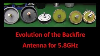
Yes, this antenna looks more like a other form of a Spironet Antenna (SPW) than a Quadrifilar Helix. Because all ends of the "leafs" are soldered at the top in the center of the cable.
I don't know it exactly while I'm still searching for a detailed tutorial, but I think one short and one long "leaf" have to be soldered at the top center cable and the other long and short "leaf" have to be soldered on the outer cable at the top.
Hi Andrew, I read that usually QHA are quadrature fed, with a 'long' and 'short' loop. Your designed is both loops end fed to the center/signal conductor.
Also, the direction of the twist is opposite in QHA, resulting in L/RHCP with 'endfire' or "backfire" propagation respectively. So in your case, the helix twist is actually a LHCP directed downwards towards the antenna stem "backfire", and needs a ground plane/reflector to direct the beam upwards into RHCP.
I made and tested a couple of these today on 5645mhz (I like to use the lower frequencies on 5.8). One I made with just 3 elements. The one with 3 elements performed slightly better than the antenna with 4 but no better than cloverleafs.
Still fun to have a tinker with them.
Hey Andrew, thanks for the tutorial on this awesome antenna. I’ve been making a few for myself as well as friends and have the means to check SWR return loss on SPec analyzer. I’ve make a few with beautiful frequency response using your exact measurements and have noticed that when I increase the distance from base to top of elements it completely kills swr. Just curious.... where have you derived the 20mm distance from? Online calculators for quadrifilar antennas? Anyways.... great job thanks. I’ve flown out around 1/4 mile and tested two on diversity set up, they work well and definitely look very nice!
Excellent information and presented in a clear and understandable method - thank you, Andrew!
looks like a great design i look forward to building one
Thanks for the inspiration to make my first antenna. It works fine on my little micro quad for fpv though due to windy days here i havent flown it much but on a walk away test it works well. Now for more.
Thanks for your great tutorials Andrew :) i've made one tonight and it is my first antenna ever but first test showed no difference with my chinese cloverleaf on the tx side, tomorrow if the weather is good i will give it a try and post my results here :) Thanks again keep the wonderful tutorials coming up :)
It might be a good idea to find some means of checking the VSWR before trying it on the Tx side. A nice companion project might be to demonstrate how to test the VSWR on such homebuilt designs, so the Tx does not get blown. :)
Very interesting. Let's try to build one and see the result. thanks for another cool video
+Hobbynation Your welcome let us know how you get on.
+andrew mcneil s815.photobucket.com/user/junior_wardogs/media/IMG_2974.jpg.html?sort=3&o=2It worked very well !!!
Thank you for sharing so many projects with us.
Unfortunately where we fly there is a lot of interference and could not test the range but I am very satisfied with the result.Fully satisfied my need.
Thank you again.
+Hobbynation hi mate! did you already test your quadrifilar antenna? And is it better than cloverleaf?
I have built this antenna, planning to use it on a receiver, instead of a skew planar. Initial tests in my apartment did not show any difference in penetration compared to my skew planar. If the weather allows I will test them in flight.
Another awesome video, thanks andrew.
How do you go about actually theorizing the design, as well as testing it's optimal design?
wow, great idea.. i will try it by myself and test it.-. i have a signal generator and spectrum analyzer capable of 5.8ghz so i can measure how good it actually performs
Hello Andrew, great video. what type of coax did you use for the stem? Did you skin all the outer plastic away and just left the braid?
Great tutorial ! One question though, seems I missed it, where is the balun soldered at. Many thanks. Keep up the good video tutorials.
HI Andrew built this antenna yesterday and test flew it this morning on my Skywalkwer 1900 and not a good result for me i'm afraid. Usable distance was greatly reduced compared with my skew planar antenna. It also appeared to be very susceptible to changes in the attitude of my aircraft (ie climbing, decending turning etc). Not for me this one keep up the good work. Bill
+Andy Buckley Hi Andy yep I added the balun so looks like a no go for me. I regularly fly out 8 or 9 kms with my SPW but was struggling at 2.8 with this one.
+Andy Buckley No my ground station has a 10 turn LHCP helical (Andrews design) that works great with my LHCP SPW. The Quadrifilar was also built LHCP but I just did not see what I was expecting at distance. Anyway still worth a try am always in the hunt for a better signal ;-)
+BillHally i also am on the search for better signal , so i went 1.2 rock solid link for what we do ! haha :P
i do understand that 1.2 isnt for every situation tho
Thats a Brilliant video. Are you going to stock those i would be interested in a pair of LHT cant make smaller things shakey hands
Hi Andrew, if I try to make this kind of antenna (with 3 wires intead of 4, at 120º) to replace a cloverleaf in the Vtx, should I have to espect an increment on the range also? Thanks in advance
the alpha card showed well, to bad you can't do the 5.8, will you get something for the 5.8. my router is dual band so this is much better than the stock one
You say that the antenna you make in the video is RHCP. As I have read in several articles and patents of quadrifilar antennas :
Example one : "Backfire resonant quadrifilar helix antenna popular for
GNSS, communications and weather satellite receiving stations.
This antenna is configured for right-hand circular polarization. Note
left-hand winding sense and the feedpoint at the top of the antenna."
Example two: "Note that the forward mode will radiate as an endfire beam
and the backward mode as a backfire beam and the circular
polarization will be opposed to the sense of the helix winding
sense, regardless of the feed phase progression"
example three: "The circular polarization sense of the radiation will be
opposed to the helix winding sense regardless of the
feed phasing sense.
• If a backfire helix antenna is used with a reflector or
ground plane at the feed, the sense of the circular
polarization is reversed and the antenna becomes
endfire. The polarization sense now corresponds to
the winding sense of the helices"
example four : "Consistent with the quadrifilar helix behavior in the absence
of a ground plane, the helix winding sense is opposed to the
desired circular polarization sense. That is to say a left-hand"
Also I could see that in the top feeds everything, in other designs, two helices are fed with the positive and two with ground
I would like to know if this is true, I do not try to judge him if he did good or bad, just to know the right thing to make me
How good would this be for a TX antenna on the quad would it help with better sinal when around trees at 200mw and would the accuracy be any more critical for the transmitter getting hot if my mesurement's not 100% spot on ?.Still think I'll have a go at this one.cheers for the great video Andrew...fellow pom in Australia .
I purchased a set of these off eBay. I don't know if it was from you or not but, I need a set to mount underneath my quad. I you a seller? Also the 5.8ghz version.
Besides measurements of the wire, how do you fine tune for the specific 5.8Ghz frequency you use? Do you have some sort of antenna tuner? Great video, Thanks!
thanks great video
Hello Sir, allow me 2 questions regarding the ballum,
First: is it polarisation related? Means the direction the ballum has to be windet.
And second, the ballum is needet cause of the closed loop of the antenna, you sayd that its near a clover leav antenna so i am asking me does the cloverleave antenna also need a ballum?
Your link to the shop does not have theses antennas. Are you not selling them after all?
enjoy watching
hmm, im going to try this out. for my rx
Are you sure your bend tool is 15mm in diameter? When I tried 15mm diameter bend tool 20mm long I wrap around 3/4 around. Any advice?
So I tried making one of these and compared it to my cloverleaf antenna .. I'm not really satisfied with the result, well I'm not saying the quadrifilar I made is perfect like yours, mine was the spacing are not even... The way I tested it is, I put my minquad on our terrace, just sitting there, then I went out, pass through some houses, and just after passing one house, the signal was lost .. unlike the cloverleaf, I can pass upto 3 house.. What's the radiation pattern of this by the way?
sure would have been nice to see how you soldered that top on..Ive allways had a hard time with doing the to with skew and cloverleafs
+James Cureton Jr. pretinning is the key.
One extra thing I do is squeeze the end a little to make a flat surface about 1mm or less. Seems they line up better for some reason. And solder flows easier.
hi mate. as i understood you soldered all four pieces on the top to the core and soldered other ends to the shielding? thanks a lot.
Hi Andrew are you not doing your eBay anymore ?
Have you ever tought of making this antenna for 1.2GHz?
It could be awesome for us fpv flyers that dont use 5.8GHz ;)
does the length of the coaxial effect the signal? can I have it shorter? many thanks
Hey Andrew, could you give us the dimensions for a 2.4 GHz version? Thanks.
First of all, thanks for a great guide! I have done this antenna twice and the swr below 1.4 is around 5650mhz and below. How to re-calculate it to get 5800 center frequency?
There will be a new video on this in the summer
@@andrewmcneil Oh, great! Can't wait for it
what is the paint type that you use on your antenna builds mate?
I want to design an antenna like this, but for a frequency of 1575 MHz. How do I calculate the diameter?
Hello. i have Mikrotik WAP AC and i wand mod connector for external 5pcs antenna.
which antenna should I choose? 2pcs 2,4 ghz and 3pcs 5.8ghz.
I used in home. concrete walls in building
Pls help
Hi, so when I connect this to my video receiver for example, should the antenna placed vertically or pointing to the quad just like patch antennas?
+Jayson Ragasa "Such an antenna will produce an exact pattern as shown in figure 4 with
majority of its gain directed towards the sky with minimal back lobes
such that it does not pick up much ground noise"
ref: www.haroonkhan-rf.com/experience.html
13:04 Why cant your test it?
You say that the gain is +8db if I remember correctly. But how is the radiating pattern? Is it still omnidirectional? If we use this antenna for FPV applications, we do not want a directional antenna for the TX. As for the RX, we can use a directional antenna but we must be carefull to keep the craft in the zone where the antenna has more gain.
+MurphysLaw996 It's omnidirectional
+andrew mcneil
So you say that this antenna amplify the signal by 8db? Usually, an antenna that has gain will concentrate the RF energy in a certain region, I do not see how a passive antenna can have gain and still have a doughnut shape omnidirectional radiating pattern. From what I read on this type of antenna is that they are used for GPS and satellite applications. Their radiating pattern is still omnidirectional but instead of being kind of spherical, the x and y axis are compressed and the z axis is expanded. It's good for satellite reception but might not be that good for FPV (for transmission).
+MurphysLaw996 Hi Murphys it does not have the same directional beam as a true Quadrifilar due to the way I had to adapt it. The Quadrifilar owes it's circular polarised properties not just to the shape of the elements but also due to the way it is wired and fed. This version works in the same way a cloverleaf works relying on the shape of the elements to produce a circular polarised patten. But it will have nulls top and bottom so I would think it would work more defectively mounted on it's side if using on a quadcopter.
+andrew mcneil
I just ordered some 50ohms semi-rigid coax on ebay... I'm just too curious to see the performance. And they seems a bit easier to make than cloverleafs since the point where the elements connect to the ground is further away from the point where they are soldered to the central conductor. I'll be able to use the spectrum analyzer function of my SDR to see if I get 8db more gain compared to a cloverleaf antenna...
Self-editted. I have now read the rest of the comments. Already answered. I might suggest possibly scanning through and summarizing the main questions and concerns throughout these comments, and then addressing them in an opening description text. I gain much from such informative youtube videos, sometimes even more from the comments, but unfortunately it can be very time consuming to fish through the comments to piece together a more complete picture in response to what prove to be the most common and useful questions. This may make future responses easier by a simple "please see the new text description for the video". But please, do not read that wrong. I am grateful for so many of these fine videos, and I full understand they are voluntary and do take time to plan and record and edit and post and respond to. So don't miss the big thank you in this comment. :)
thank alot.i want to use qha to gps frequency can u tell us your antenna measure in lambda for custom calculation?
Have you ever tied that design for 2 meters? or and of your 5.8's antennas?
+buzzsah I know it must be larger but maybe fun to try.
+buzzsah Hi Buzzsah I don't have any experience with anything below 1.8GHz but like you say should just be bigger.
is this for the transmitter or receiver?
do you have a video that explains baluns
Making these JB Weld in your friend.
please explain how that balun working???
What do you paint these with? just normal paint.
+Lebalusch I'd say plasti dip is a good option too.
Could you please put a materials list up
hi way you can't tests on 5.8ghz ?
Can you build a half sphere antenna for 2.4 Ghz?
Link to the shop doesn't work
8dbi, so very flat donuts shaped right? i dont think its good for quads that change angles every half second
+Calvin C Hi Calvin it has a radiation patten identical to the cloverleaf.
+andrew mcneil Sorry but if that is the case then there is NO gain. All gain from antenna's is derived from squeezing the radiation pattern. If this antenna has a whopping 8dbi gain then it has to squash the donut pattern flatter which means its better for the receiver (as long as its not on your head). Quads or Aircraft bank. Great tutorial thanks.
Then it's gain can't be higher. As he said, antenna's increase gain by squeezing the pattern so there's more radiation in some directions and less in other directions.
This one achieves increased gain by being a hemispherical antenna, NOT an omnidirectional antenna!
I want one
Just want to remind everyone that it is a horizon to horizon antenna. IT IS DIRECTIONAL!
this is not my field, what do you mean with Horizon to Horizon? to me this design looks exactly like a stubby, an axii, a rushfpv cherry or a foxeer lollipop, and they are omnis
@@haythamfpv This type of antenna has a strong half half sphere radation pattern. This type of antenna is usually used for orbiting satellites. Since they travel horizon to horizon. So this would be a good antenna, just don't point it horizontally because you will lose half of your radiation pattern.
If you search for images "quadrifilar helical antenna radiation pattern" you'll see what I mean.
@@1kuhny thank you a lot!
Will this design work for both the tx and the rx?
+Jens Utbult Yes they work fine for both
I respectfully remain a bit nervous about the Tx side without a reliable means of testing VSWR. Could you suggest a simple setup/method to at least confirm that it is 2:1 or better, with a cheap Tx, before risking the flight Tx? If we are building antennas, might as well have some nifty inexpensive homemade test tools/methods to check VSWR at 5.8ghz, yes? Here is an example of some testing methods to verify the effectiveness of homemade CP antennas against a commercially made baseline:
ua-cam.com/video/jlz8MTTntGI/v-deo.html
Now we could use some test for VSWR as well for the sake of protecting the Tx output circuit. My schedule is full for awhile, but if others could link videos or inexpensive meters, that would be handy indeed.
can i buy two from you?
what do you paint your antennas with please?
+MrBlackbrabus1 acrylic paint
+andrew mcneil brilliant thanks....I'm just making a set now....nice a simple really....great instructional video
+andrew mcneil I had a go at making one this evening ..... still needs epoxy and painting but not bad as a first try
[URL=s185.photobucket.com/user/blackbrabus/media/20150924_220913.jpg.html][IMG]i185.photobucket.com/albums/x209/blackbrabus/20150924_220913.jpg[/IMG][/URL]
+MrBlackbrabus1 The link is not working
+andrew mcneil
i185.photobucket.com/albums/x209/blackbrabus/20150924_220913.jpg
RHCP or LHCP?
+Constantinos Pitsakis The one in the video is RHCP
I have the same question in the video says RHCP but in theory I think it is LHCP
Yes, there is some confusion that could use some further explanation. An old ARRL antenna book I have only details a bilfilar made with coax. It shows a quadrifilar but does not explain it fully and has no construction details, saying only that it is in use on satellites. I need to read it again to better understand exactly what the actual CP is radiating from the antenna, but I am not sure if it would differ from a different construction. I'd like to believe that one can always tell the polarization by looking at the physical spirals, as with a cloverleaf, but RF is not always so easily visually determined, and is subject to where volts and amps terminate or reflect, etc.
As a convenient reference, regarding the typical popular cloverleaf antenna, one looks at the antenna in an upright profile view, ground at the bottom, connected loops at the top, similar to how it would be mounted vertically on an aircraft. Now slowly turn the antenna (spin the coax in the fingers) until one of the lower legs is pointing right at you, out from the coax. the "leaf" then bends off in the direction of the polarization. If it bends up to the right it is RHCP. If it bends up to the left it is LHCP. A question then becomes, "Does this hold true also for this particular quadrifilar antenna design?"
If anyone has a thoughtful answer to that question, Please explain your method and conclusion if it differs from the cloverleaf, and why, so it can also be responded to intelligently by the community for the benefit of all of our better understanding and better communication. Also, if anyone has done a thorough RF experimental analysis of this particular quadrifilar design, and posted a video or blog entry, etc, please post the link in these comments for the benefit of us all.
Thank you Andrew, for another fine video of an antenna that is fairly easy to construct with care and patience.
+FPVunlimited Drones & FPV
I see that further down in the comments, you more thoroughly expressed your concerns. As of feb 2018, it is unfortunatedly not yet answered. I hope we have a response from someone soon to put the issue to rest. If you have resolved your doubts since then, please update your response. Of course, experimentally, it is easy enough to answer by testing received signal strength (or a simple range check) with both a RH and LH "known" cloverleaf (in separate tests of course). If anyone has done so, please update us. Thank you.
None! This is not quadrifilar, it has no means of introducing phase quadrature, not a real balun etc. This is just some guy playing with wires and imagining he is antenna expert. Oh, and yours cloverleaf's are also bullshit, not cp, no balun, just toys, no science!
sorry if you have already answered this
Not quadrifilar, not cp, no real balun, total bullshit!