A more flexible solution would be to add controls for continuous _and_ momentary operation... a three position On-off-On switch would allow continuous operation, and the existing up/down switch would be paired with a pushbutton (or two pushbuttons) to allow easier operator control.
Hello, Great video! I bought the parts for this and built one. I actually got it to work, will this perform better using say 24volts as opposed to 12volts? Thx
Do stepper motors run cooler with driver is set to less steps per revolution? Do stepper motors run cooler with driver is set to less Amps? I am using Nema 23 57x57x56mm, 23HS2430B, 57BYGH056 Using DM556 Driver ZK-SMC01 stepper motor controller AC 110v to 24v Power Supply 20A Max Using on a machine that runs for hours at a time. Motors run feed screw at constant speed one direction then the other direction for 10 minutes before reversing then repeats. Driver is now set to 2.7A -1600
Okay, excellent. I need to clear a doubt: There in the circuit link, the circuit has MODE1, MODE2 and MODE3 in "VCC" and so we will have microsteps.. I want "Full step"">>>> I have to put them all in "GND" or leave them disconnected? Congratulations for the article/Video. Thank you from Rio de Janeiro/Brazil.
Another question: with only one pulse generator, I could put in four sets of this, in parallel. So everyone would have the same speed. keeping common GND? Thanks.
I love the circuit. I wanted to run a window shade up and down with a stepper motor and didn't want waste and Arduino. This would work great (with a little tweaking). One question. Could a 4014 work?
I built the circuit but dashed if I can get it to work with exact components and stepper motor as per circuit diagram. Tried other SM's with same result... failure. Something wrong in the circuit diagram? Also changed main components in case one had something faulty there. Still failure. This is just the sort of circuit I was looking for but sad I can't get it to work.
I tried this project Its working but Drv8825 is heating And speed is so slow How can i solve this problem And how to increse speed of motor Plz help me
Just ordered the parts for this controller. Awesome channel! Can you add limiting switches for this controller when attached to slide rails? Thank you for your channel.
Cool! Would it be possible to add a button which makes the stepper rotate 100% in addition to the potentiometer? (Would be nice for a power feed project:) keep up the good work!
I set up the circuit. But it doesn't work. I thought there might be a problem with the components. I ordered the combinations again. I re-set it up. But it didn't work again. I got support from a professional electronics engineer. And it didn't work again.
Hi.i want to make motion like elevator by means of step motor that give me up and down motion and every time I press botton to stop the elevator comes down and stop if everywhere it be.like movement of dumper motor in split air condition that swing motor goes up and down and when off the unit it retracted automatically.i want to know what driver or module i need
nice but it is not useful when the motor starts to rotate when i plug it, i need to press the button to rotate clockwise and press another button to rotate in anticlockwise, how to do it ? this will be much useful to me .... thanks
I don’t see why not. Use your limit switches to operate some relays. Many relays have normally open and normally closed contacts. In this way I think you could have it hit the end of travel limit and either stop or reverse depending. He already showed that the motor defaulted to one direction and by toggling power it would change direction. The other option should be to kill power and stop the motor. Go find some videos on Bosch relays. And relay logic in general. I’m sure there are more elegant ways, but I’m a mechanical guy and relay logic is fairly mechanical so it suits my way of thinking.
Well, the available torque of any stepper is a function of speed (Google “stepper motor torque-speed curve”). The potentiometer isn’t having the effect you think it is though, if I am guessing the origin of your question correctly. The potentiometer is controlling not the voltage amplitude to the motor, but the voltage pulse frequency the motor driver is receiving on its control input.
Simple DIY: Instead of arduino or microcontrollers, let's build a controller from scratch. While you can control it with 2 caps, a button and a variable resistor...
Awesome video!!! I have a micro 4 wire stepper motor I would like to get running. Would you be willing to make me a diagram for that motor? Thank you in advance for your time all the best! Darrell Pedersen
Have anybody got this to work? I bought all the components. Assembled it on my breadboard. And the motor kind of turns. Sometimes it takes off for a while and then stutters and it just seems to be no consistency. Anyone have any ideas?
From the data sheet. Reset and sleep pins must be high to enable driver. That's pins 5&6. The circuit that is shown in the video links 5&6, but doesn't connect that bridge to +5 Volt supply. Suggest you modify your circuit and try again. For full speed, disconnect pins 2,3,&4. Connecting those pins to 5 Volts as shown gives minimum speed, ie. 1/32 step. That driver circuit has a miniature potentiometer on it. If you start running a motor on load, you can burn it out. It's there to provide current limitation, and there is a setup procedure to follow. That will also cause running problems if set too low at the factory.
How to make a stepper motor turn without a driver ic... step 1: buy a driver ic. I dont know if anyone was paying attention to the title they clicked on but, he literally contradicts himself immediately.
@@Jordan_Fernando All I can suggest is to start substituting parts. First check the resistance of both motor coils, or connect a drill to the shaft and monitor the output, ie., drive it as a generator, disconnected from the 8825. If it seems OK, replace the 8825 assembly. If still no go, get someone to check how you have wired it up, because if you are over familiar with what you have done, you can over look an obvious wrong connection, no matter how many times you look at it. If you have an oscilloscope, check that you are getting the correct waveform at the point where the motor connects to the circuit.
@@Jordan_Fernando Just had another think about your problem. On his circuit, he left pins 1, 3, 5, and 13 of the 74HC14 open. They should be connected to ground or the 5 volt supply, whichever is easier, so have you got a square wave at pin 8 of the driver board? It's a cmos device, so all unused inputs must be connected, or strange things can happen. The motor that he is using runs on 12 volts. Are you supplying the correct voltage to yours? To make the motor run 32 times faster for any given input frequency, disconnect pins 2, 3, and 4 of the 8825 board. If you get it working, let us know, because others are having problems, judging by the comments. I've never used his circuit. DON"T GIVE UP!
![Electrical Projects [CreativeLab]](http://yt3.ggpht.com/ytc/AIdro_nXuaCebPi8RjzINYxrETo1-K9WQerCEIndpQMoSs0BfQ=s48-c-k-c0x00ffffff-no-rj)


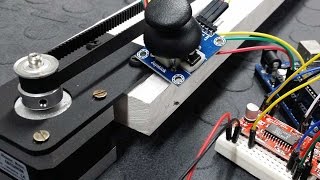


Awesome build! I've never thought of mounting components horizontally, like you have mounted that switch and potentiometer!
A more flexible solution would be to add controls for continuous _and_ momentary operation... a three position On-off-On switch would allow continuous operation, and the existing up/down switch would be paired with a pushbutton (or two pushbuttons) to allow easier operator control.
Genius! I have been looking all over for something like this for some of my holiday animation's.
Hello, Great video! I bought the parts for this and built one. I actually got it to work, will this perform better using say 24volts as opposed to 12volts? Thx
I'm writing after prolonged use. It works correctly. The only shortcoming would be better if the buttons were right left and stop.
Great video! I have a 28 VDC stepper motor with 3 coils. Do you have a suggestion for a driver circuit?
excellent soldering skill :)
Thank you..♥️ I got my requirements for making dough blender for my mother .. thank you again ♥️♥️🌸
Do stepper motors run cooler with driver is set to less steps per revolution?
Do stepper motors run cooler with driver is set to less Amps?
I am using Nema 23 57x57x56mm, 23HS2430B, 57BYGH056
Using DM556 Driver
ZK-SMC01 stepper motor controller
AC 110v to 24v Power Supply 20A Max
Using on a machine that runs for hours at a time. Motors run feed screw at constant speed one direction then the other direction for 10 minutes before reversing then repeats. Driver is now set to 2.7A -1600
Okay, excellent. I need to clear a doubt: There in the circuit link, the circuit has MODE1, MODE2 and MODE3 in "VCC" and so we will have microsteps.. I want "Full step"">>>> I have to put them all in "GND" or leave them disconnected? Congratulations for the article/Video. Thank you from Rio de Janeiro/Brazil.
Another question: with only one pulse generator, I could put in four sets of this, in parallel. So everyone would have the same speed. keeping common GND? Thanks.
I love the circuit. I wanted to run a window shade up and down with a stepper motor and didn't want waste and Arduino. This would work great (with a little tweaking).
One question. Could a 4014 work?
Great video. But is there a way to see the rpm of the motor while operation or add a rpm controller.
I built the circuit but dashed if I can get it to work with exact components and stepper motor as per circuit diagram. Tried other SM's with same result... failure. Something wrong in the circuit diagram? Also changed main components in case one had something faulty
there. Still failure. This is just the sort of circuit I was looking for but sad I can't get it to
work.
Same here.
I tried this project
Its working but
Drv8825 is heating
And speed is so slow
How can i solve this problem
And how to increse speed of motor
Plz help me
Would be very appreciated if u would be kind enough to let me know whether it can be speed up to 1000 - 2000 rpm or not?thanks.GBU
Just ordered the parts for this controller. Awesome channel! Can you add limiting switches for this controller when attached to slide rails? Thank you for your channel.
Outstanding work. Simple but very educational. Great job. Cheers.
Cool! Would it be possible to add a button which makes the stepper rotate 100% in addition to the potentiometer? (Would be nice for a power feed project:) keep up the good work!
I have A4988 driver... I assume your controller will work also for A4988.... I will try this week... thanks for the design
Hey did this end up working? any adjustments needed?
I build this PCB according your wideo but not work.
Can I get any help?
I set up the circuit. But it doesn't work. I thought there might be a problem with the components. I ordered the combinations again. I re-set it up. But it didn't work again. I got support from a professional electronics engineer. And it didn't work again.
its not moving the engine
just hear szszszsz...what to do?
what is the lowest rpm you get from the motor ?
can use for unipolar stepper motor (6 wire stepper motor) ?
this project is beautiful. how can i make a pcb? can you help me?
Is it possible to replace the drv8825?ill be using TB6600 microstep driver.(same setup) Thank you.
Good video, I am going to build one of these my self
Hi.i want to make motion like elevator by means of step motor that give me up and down motion and every time I press botton to stop the elevator comes down and stop if everywhere it be.like movement of dumper motor in split air condition that swing motor goes up and down and when off the unit it retracted automatically.i want to know what driver or module i need
Do you have a video for the other drivers selling by the supplier??
nice but it is not useful when the motor starts to rotate when i plug it, i need to press the button to rotate clockwise and press another button to rotate in anticlockwise, how to do it ? this will be much useful to me .... thanks
hi, is it your circuit worked?
@@p.7555 yes, 1 switch for change the direction, and 1 button i press it to drive ,
Can we use smaller breadboard which has 170 points in it??
Can i stop the motor at 90 degree rotation using push button
I'm new to step motor. What is different between drv8825 and uln2003?
I want buy a complate controlar of stepper moter
What is the price of this device
Hello, is it possible to buy the controller from you please?
Do you have tutorial on how to control stepper motor by rc transmitter?
Can i provide pwm via Bluetooth
Dear. Stepper Motor control revars and forward in WIFI? Please areng the controller. Thanks
The slowest speed is still very fast. How to speed down even more?
Hi I'm Matthew, what are the names of the spare I need to build
How much constant pressure can a stepper motor be put under
Simply, brilliant.
No sufre calentamiento el motor o los componentes?
Pls i want one of this controller, how can I get it
Possibly if it can be send to nigeria
Can 2 limit switches be added to the controller. If so, How?
I don’t see why not. Use your limit switches to operate some relays. Many relays have normally open and normally closed contacts. In this way I think you could have it hit the end of travel limit and either stop or reverse depending. He already showed that the motor defaulted to one direction and by toggling power it would change direction. The other option should be to kill power and stop the motor. Go find some videos on Bosch relays. And relay logic in general. I’m sure there are more elegant ways, but I’m a mechanical guy and relay logic is fairly mechanical so it suits my way of thinking.
What about the torque strength of the motor if a potentiometer is installed like that
Well, the available torque of any stepper is a function of speed (Google “stepper motor torque-speed curve”). The potentiometer isn’t having the effect you think it is though, if I am guessing the origin of your question correctly. The potentiometer is controlling not the voltage amplitude to the motor, but the voltage pulse frequency the motor driver is receiving on its control input.
great idea and the diagram is the same for a Nema 23 ?
I would think so but set your vref as to not over load your driver.
Nice video, thank you for sharing it :)
Hi Man... Please... Its project work in Nema 34 with 6 wires? Congratulation!
Did you find out if a Nema 34 works with the above controller?
if the direction switch is made 2 pieces, how is the circuit?... thank your sir
Парень, ты очень помог мне! я бы тебе и 10 лайков поставил, если это возможно было!
Its run without programing sir ?
Simple DIY: Instead of arduino or microcontrollers, let's build a controller from scratch. While you can control it with 2 caps, a button and a variable resistor...
Could you explain how?
Can i use 5v dc stepper motor with this circuit?
And is the result are same?
CAN I USE A4988 STEPPER MPTPR DRIVER?
Is the microchips programmed
0:38 ...or DRV8825?
how can be ride without button ?
So nice. Excellent.
Can I use step motor
Thank you 🙏
Awesome video!!!
I have a micro 4 wire stepper motor I would like to get running. Would you be willing to make me a diagram for that motor?
Thank you in advance for your time all the best! Darrell Pedersen
Can speed 1500 rpm?
Have anybody got this to work? I bought all the components. Assembled it on my breadboard. And the motor kind of turns. Sometimes it takes off for a while and then stutters and it just seems to be no consistency. Anyone have any ideas?
From the data sheet. Reset and sleep pins must be high to enable driver. That's pins 5&6. The circuit that is shown in the video links 5&6, but doesn't connect that bridge to +5 Volt supply. Suggest you modify your circuit and try again. For full speed, disconnect pins 2,3,&4. Connecting those pins to 5 Volts as shown gives minimum speed, ie. 1/32 step.
That driver circuit has a miniature potentiometer on it. If you start running a motor on load, you can burn it out. It's there to provide current limitation, and there is a setup procedure to follow. That will also cause running problems if set too low at the factory.
How to make a stepper motor turn without a driver ic... step 1: buy a driver ic. I dont know if anyone was paying attention to the title they clicked on but, he literally contradicts himself immediately.
Driver ic is a non programmable device since microcontroller does
does this work with a nema 23 ?
I'm not sure why it wouldn't. But I would make sure set the vref correctly as to not pull too many amps through the driver.
How to increase torque power
Your code not compaling. Sir pls halp me
I will make as per your diagram but not working
direction switch not work the same direction
I couldn't get it to work either. It just locks the motor.
Pins 5&6 need to be connected to 5 Volts, or it stays in sleep mode. Give it a go.
Nice sir
very very very nice !!!
How much cost ?
Please diagram wire TMC2208 for stepper motor 24V ex 3D print 🙏
Great Dude :)
Thanks!
Keep up!
Not working. Motor just make a humming sound. And the driver gets really hot
Because he never showed you how to set the current limiting potentiometer on the DRV8825, and pins 5&6 should be connected to 5 Volts.
@@peterrhodes5663 I have set the limit of the drv8825 and have connected pins 5&6 to 5v but still not working, do you have any ideas?
@@Jordan_Fernando All I can suggest is to start substituting parts. First check the resistance of both motor coils, or connect a drill to the shaft and monitor the output, ie., drive it as a generator, disconnected from the 8825. If it seems OK, replace the 8825 assembly. If still no go, get someone to check how you have wired it up, because if you are over familiar with what you have done, you can over look an obvious wrong connection, no matter how many times you look at it.
If you have an oscilloscope, check that you are getting the correct waveform at the point where the motor connects to the circuit.
@@Jordan_Fernando Just had another think about your problem. On his circuit, he left pins 1, 3, 5, and 13 of the 74HC14 open. They should be connected to ground or the 5 volt supply, whichever is easier, so have you got a square wave at pin 8 of the driver board? It's a cmos device, so all unused inputs must be connected, or strange things can happen.
The motor that he is using runs on 12 volts. Are you supplying the correct voltage to yours?
To make the motor run 32 times faster for any given input frequency, disconnect pins 2, 3, and 4 of the 8825 board.
If you get it working, let us know, because others are having problems, judging by the comments. I've never used his circuit.
DON"T GIVE UP!
Did you ever get it to work? I’m having the same problem.
I like that, I just want to ad wifi.
Please diagram control tmc2208 🙏
slow rpm
Disconnect pins 2,3&4 or ground them for max speed.
not working
yes, me too
Connect pins 5&6 to 5 Volt supply.