555 Timers - How Bistable Mode Works - The Learning Circuit

Вставка
- Опубліковано 25 лип 2024
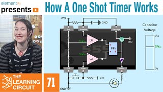
- Karen has been digging into 555 timers for a bit now. In a previous video, she did an overview of the 3 different modes in which a 555 timer can be used. In this video, Karen goes into further detail about one of those modes: Bistable. In bistable mode, signals at two inputs are used to manually set the output of the 555 timer high or low. For example, one button could trigger the output to turn a light on, while a second button could reset the output to turn the light off. This video goes over what is happening in the 555 timer internally to make this type of circuit work. Karen also presents a practical example on a breadboard to show using a 555 timer in bistable mode: bit.ly/2wF2xtP
Engage with the element14 presents team on the element14 Community - suggest builds, find project files and behind the scenes video: bit.ly/2MFMG0v
Visit the element14 Community for more great activities and free hardware:
Tech spotlights: bit.ly/2KLz0TS
Roadtest and Reviews: bit.ly/2KH4fj3
Project14: bit.ly/2wPnajx - Наука та технологія


You do the best job of explaining things. It must have taken a great amount of planning. Your illustrations are excellent. I have learned so much from your videos. Thank you.
No te había encontrado en youtube hasta ahora, !!!! Tus videos son excelentes !!!! aunque no entiendo el inglés. Excelentes imagenes. Felicitaciones !!!!
Beautiful explanation 👏👏👏
Excellent description of how this configuration is set up and functions.
(I can't help it; I learned to call it the "five fifty-five timer" back when it first came out, and hearing it called "five five five timer" clashes with that. 😁 No worries; keep up the good work!)
Finally teacher you are back after a long time
i was using 555 timers since 1976 some things don't die
Yes, it's such a neat little building block component. It's a happy middle ground between too simple and too complex. These days so many people see a tech problem and want to throw an Arduino or Raspberry Pi at it, when a few components like 555s and such can be simpler and reliable. Yes, being able to make changes via software is great, but overkill for many applications.
thanks for your simple discreption
about 555 ic
Question, why would you use the 555 timer in bistable mode instead of just using a RS flip flop IC?
The NE555 can be used as a PWM amplifier by using the CV pin, There are kits that build into a NE555.
Is that a good way to debounce an input for an arduino? Or would that be over kill?
Karen it is good job, thanks.
can u show the final circuit diagram with two switches at the end? or put in description because its confusing at the end
New subscriber and working on and building one now. Do those buttons come in an accessory package? What size capacitors did you use? Anyway great video excellent channel and instructor Artie ❤️
You can buy all the parts individually. I have the BoM with product links listed on the e14 Community. The link is in the description above.
I used a 0.01uF ceramic cap. And thank you!
hey i love your videos !!
looking for an astable monovibrator tutorial!!
apu kazti to doti C828 transistor and resister diye e to hoye jai...jekhne doto transistor diye hoye jai sekhane ami atogolo transistor nebo kano...555 ic mone hoy 2tir vesi transistor diye toiri....opochoy kari soytaner boon.....with love amd.
Hi Karen! If the comparator outputs high why the bulbs output is low?
They did not show the internal flip flop so yeah... they messed up, look up a proper block diagram for it on Google.
@@NETypeMCPERedstone I tried to simplify to just cover what was needed to understand how this mode works. You can check out my other 555 video for a more in depth explanation that includes the flip flop. ua-cam.com/video/oZzjmAbyyIQ/v-deo.html
But how does the output stay latched? Is there an SR latch or something between the comparator outputs and the output pin?
Yes there is they did not mention it.
@@NETypeMCPERedstone yes there is an SR latch
so if you use this to power a motor, will the motor only get 1/3 of the battery voltage?
You wouldn't use this to power the motor directly. For that you would connect the motor directly to its power supply through something like a relay, mosFET or BJT. You would then use the 555 to switch these on or off. Of course this will only give you off/on control. Controlling the motor's speed will need a way of creating a PWM signal.
Nice
I understand the circuit thanks to this video, what i don't understand is practical applications vs using a latching switch. I must be missing something?
Me hubiese encantado que los OP AMP estuviesen sus entradas disponibles en pines externos. Así se harían maravillas con el 555.
Cool....now I'll make a chess match clock with two players toggling the clock with switch
Changing stepper motor direction with limit switches by hitting them.
And make a step generator on 555 timer with a variable resistor.
Cool application idea!
hi, i'm working on the same application. Did yours function properly ?
You are awesome
What happen if both button pressed at a time?
Excellent question!
1) Try it and see! (Learn by doing. 🙂)
2) One thing to consider: Chances are they won't both make contact at the _exact_ same time. One will end up first, the other last. That's why debounce circuits are needed, since the switch contacts can literally bounce, making and breaking connection a few times until they stabilize.
Once the trigger is set to ground, output goes high. Ok . But as soon as push button is released , it will connect to vcc . So trigger pin goes on high voltage. How does output remains high. Kindly explain. I am new to electronic.
After the op amps there is a flip-flop which holds the latest state. The flip-flop is not shown in this video.
Application I'll use : When the push button is pressed the motor will turn ON (fills the water in the tank, If the water tank fully filled) then motor will automatically turns off
What is work of capacitor here?
The way I use to understand comparitors and op-amps. When the input equation is true the output goes positive. When it's false the output goes low.
Kindly explain
Hi Karen
I generally like these videos and find them very useful, but found this one very confusing until I read through the comments.
6:05 "to the breadboard" looool
this circuit can be used to design a water level controller of domestic water tank. I have done this project with my students
more details, please
Does it connect to a water pump or something? I've thought about making an automatic plant watering system for my succulents using moisture sensors, but wasn't sure how to control the water other than a solenoid somehow.
@@maker_karen1785 Definitely it can be done with this circuit .
@@var67 exactly
@@grindel80 when the level of the water goes below the lower threshold point circuit is negative triggered ,o/p goes high and that makes the motor ON ,connected with a relay transformer . when water is filled up in the tank and reaches the upper threshold point ,the circuit is positive triggered ,o/p goes low and switches OFF the motor .
Hi
I am new to electrical engineering. For those of you all who are professors or have been in this field for a while, please tell me your story. I need motivation
I think you guys messed up.
Where is the internal flip flop of the 555 Timer?
The block diagram at 4:15 is wrong. I can understand the lack of discharge transistor since it isn't used but the flip-flop is needed.
It's not really wrong, just omitting some detail. She describes the behavior correctly and in detail. If you're interested in the exact details of your timer, you should look at the datasheet.
but its a big important detail being omitted. the sr latch is the whole reason the output remains in its steady state after the buttons are released. if the output came directly from the comparators, as depicted, then it would not have a stable mode.
@@xedover Yeah it is an important detail.
@@NETypeMCPERedstone Yeah, you can't really say something is in detail if it misses a big detail... That is just... Well... That's just logical thinking, surely?
If you're 555, then I'm 666
Hmmm... Got that a bit wrong. In school when doing Electronics we started out with a 555 and there is some pretty remedial stuff missing. Like how the output stays latched.
I get they are trying to simplify it, but if they could teach it to a bunch of 14 year olds...
I cover a more detailed explanation of the internals here. ua-cam.com/video/oZzjmAbyyIQ/v-deo.html
If it at least worked i would be happy
Sorry that was clear as mud
The explanation of how this circuit works (and the internal architecture of the 555 timer) is very wrong in almost every way. The outputs of the comparators in a 555 timer do *not* connect directly to the output pin (which is just as well because if one was high and the other was low, it would be an internal short circuit). They go to the inputs of an SR latch. It is this latch that "holds" the state. A comparator by itself would not latch either output state in the way described once the button that activated it was released. To suggest that it would is very misleading. Really, it would be best to take this video down and reshoot it with a proper explanation of how the circuit works. That would be an interesting video.
Thanks for this. I was wondering how state could possibly be maintained in this setup, given that the outputs don’t connect to any input.
Another useles video with not working circuit