What are 2-Wire and 4-Wire Transmitter Output Loops?

Вставка
- Опубліковано 18 вер 2024
- ▶ C'mon over to realpars.com where you can learn PLC programming faster and easier than you ever thought possible!
=============================
▶ Check out the full blog post over at
realpars.com/t...
=============================
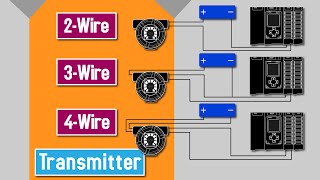
In this video, we’re going to take a close look at 2-wire and 4-wire transmitters and discuss where they are used and why. We’re also going explore wiring configurations and how transmitters are connected to a PLC.
Before we get started, you might want to review our video called PLC Analog Inputs and Signals (realpars.com/p....
A transmitter is an instrument that converts the small signal from a sensor to a signal which represents the variable being measured.
Transmitters come in all different shapes and sizes and connect with several types of sensors.
The transmitter output signal representing the variable being measured can be voltage or current.
A transmitter analog output loop contains the transmitter, power supply, and the receiving device which could be a PLC or DCS.
Just like any other instrument, a transmitter needs a power supply to operate. But, is it a 2-wire or a 4-wire transmitter?
The actual wiring connection between the transmitter and the power supply depends upon which type it is.
A 4-wire transmitter has 2 wires connected to a power supply, and 2 signal wires connected to the PLC.
The power supply can be AC or DC depending upon the vendor and model.
As its name states, a 2-wire transmitter has only 2 wires.
In a 2-wire current loop, the transmitter, DC power supply, and PLC are connected in series.
Not only are the 2 wires providing power for the transmitter, but they are also the signal lines!
Earlier we said that the transmitter output can be either current or voltage. Current is by far the most common transmitter output signal for many reasons.
One reason is if the wires between the transmitter and the PLC are very long, there could be significant voltage losses across these wires.
Regardless of the length of wire in a current loop, basic electrical theory tells us that the current is the same in the circuit regardless of where that current is measured.
=============================
Missed our most recent videos? Watch them here:
realpars.com/w...
realpars.com/c...
realpars.com/f...
=============================
To stay up to date with our last videos and more lessons, make sure to subscribe to this UA-cam channel:
goo.gl/Y6DRiN
=============================
TWEET THIS VIDEO ctt.ac/oEPnm
=============================
Follow us on Facebook: / therealpars
Follow us on Twitter: / realpars
Follow us on LinkedIn / realpars
Follow us on Instagram / realparsdotcom
#Transmitter #RealPars #PLC


I work as an instrumentation tech and these videos have been infinitely helpful Thank you for you work.
Hi Geomar,
Thanks a lot for your kind compliment! We are always extremely happy to hear such positive feedback! If you ever have any questions, feel free to reach out to us.
Happy learning!
Please explain wiring, when we use barrier in the loop in two wire communication. For example of we use P&F barrier then where to put this barrier in the loop?
Using common sense I can tell that...just before the TB we can put barrier. But I have seen two wire communication where power supply, transmitter and PLC are not in series.
Dear Realpars team,
Please also explain 1) what is 3 wire transmitter and 2) application of usage 3) how to hook up 3 wire transmitter to a PLC or DCS cicuit.
Thanks in advance
Best Regards,
PC Raju.
Hi Raju,
Thanks for your comment!
Great suggestions for future video courses, I will make sure to forward that to our course developers. Thanks for sharing and happy learning!
This channel is blessing
Thank you, Bhushan!
Nice video...
Please make a video on superimposed signal
Thanks for sharing your suggestion with us! I have sent this over to our course developers.
Happy learning!
Very helpful. Clear explanation.
Kudos!❤
Glad it was helpful!
Congratulations, you make the learning easy
Thanks for your support, Ricardo!
Good explanation.
I think in 2 wire communication power supplied from in-build IO module in PLC
Sir need transmitter calibration videos ❤
Thank you! I'll share this with our team. Stay tuned!
Good explanation. I would like to know if there is any advantage of one system over the other.
Great suggestion! I will go ahead and pass this on to our course developers for a possible future video course.
Thanks for sharing and happy learning!
Great video.... so well explained along with visual!
Thank you so much, Jim!
great lesson in few minute.
Thank you!
It is a great channel
Could you please make a video for analog output from PLC with wiring on the card for any Allen Bradley type.
Thank you in advance.
Thanks for your topic suggestion, Gaith! I will happily pass this on to our course developers for possible future video courses.
Thanks again for sharing and happy learning!
Good information
Thank you, Tanweer!
Please dear make a video on 1st level and 2nd level inspetion of electrical equipments....thanks...
Hi Ameer,
Thanks for your comment and your suggestion. I will pass this on to our course developers!
Thanks for sharing and happy learning!
Jewel video. Thx so much.!! 👍🏾👍🏾
Our pleasure!
thank you!
Happy Learning🎉
Thank you realpars!
Just a remark; I think we should never use AC and only use DC Power supply when using 2-wire loop powered transmitter because if you use AC, then you can have Electromagnetic Interference (EMI) in your signal that is being sent to the PLC. Please correct me if I am wrong.
You are correct. A 2-wire transmitter's circuits are designed to regulate DC current, not AC.
@@realpars thanks for confirming.
It is good to explen curren and volt signales and 4 wire and 2 wire
Really helpful information
Thanks
Great to hear that!
What is the most used in industry 2 wire or 4 wire ?
Thank you for your question. Both types are widely used in the industry, and the best choice depends on the specific application and controller type. Learning both is beneficial if your role involves wiring and integrating them into your designs. These concepts are commonly taught in electrical engineering and technical schools due to their broad applicability. Happy learning!
Thanks for lesson
You're very welcome, Rahmat!
Best explained sir thanks
Thank you!
THANKS
You're welcome!
Great 👌🏻👌🏻,
That's what I'm looking for..
Great!
sir can you please explain how to use 4 wire transmeter in place of 2 wire can we inter change them
Hi Arslan,
Thanks for your comment!
That would make a great topic for a future video course. I will happily pass this on to our course developers.
Thanks for sharing!
what if the transmitter is loop powered meaning that there is no need for a power supply in the 2 wire configuration, the transmitter receives the power from PLC IO cards ?
NO. Loop powered is synonymous with a 2 wire circuit depicted in this video production. Loop powered does not require any ADDITIONAL power supply to function , but does require A power supply to function. Loop powered devices typically have very low power requirements to mitigate loop voltage drop.
Nope. You put a power supply in series with the transmitter and the PLC. If the transmitter is loop powered, then it gets its power from the loop. The PLC's Analog input doesn't provide power.
Now you could grab power from the PLC's 24 VDC power supply, is that what you meant?
In that case, yes that would work. The +24 VDC lead to the "+" lead of the transmitter. The "-" lead from the transmitter to the PLC's Analog input "+" terminal. And the PLC's Analog input "-" lead to the PLC's "-" terminal.
"The +24 VDC lead" should be "The +24 VDC of the PLC's power supply" for clarity. And you would have to decide if saving a power supply and using the PLC's power supply instead was the appropriate thing to do.
A 2-wire transmitter is technically "loop powered". If the PLC I/O card provides the 24 VDC, then a series-connected power supply is not required. In this case, the 2 leads from the 2-wire transmitter would be connected directly to the 2 leads of the PLC I/O card.
Amazing video tenks...
You're very welcome!
good lesson
Happy to hear that! Thank you!
thank you❤
Our pleasure, Kevin!
I actually want to know in an Analog I/O module card ,where does the 250 ohm resistor is placed with regards to 2 wire and 4 wire?
An external 250 ohm resistor is needed only if the I/O card is a voltage type. If that is the case, the 250 ohm resistor is connected across the input terminals of the I/O card.
@@realpars thanks
Did you stop giving certificates from your online courses?
Hi Tzell,
No, we still grant a free certificate of completion for each completed course series :)
They will automatically appear on your account.
@@realpars ohh that's perfect. Thanks ✌🏿🙏
Nice
T h a n k y o u