
Вставка
- Опубліковано 23 гру 2024
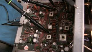
- The Michigan Mighty Mite is a very simple crystal controlled CW transmitter that uses very few parts, is easy to build, and a fun little ham radio project. Simplicity comes at a price, and that price is harmonic distortion. A low pass filter is shown that helps to dramatically reduce the distortion. This Mite is built with a 3.579MHz "color burst" crystal. Inspiration for building the Mighty Mite came from the Soldersmoke blog and podcast. More information can be found at the following links:
Lots of pages on the Michigan Mighty Mite:
www.lmgtfy.com/...
Soldersmoke blog posts on the Michigan Mighty Mite:
soldersmoke.blo...
ELSIE Filter Designer software:
tonnesoftware.c...
Jim Tonne has a number of GREAT tutorial papers on his website, including a top-notch filter tutorial. See here:
www.tonnesoftwa...
Toroid design page:
toroids.info/


Got plenty of those crystals, for sure. Also plenty at four times the frequency at 14.31818 MHz, which was used in all sorts of stuff. Dividing it by 4 gets you back to the colorburst frequency (and from there all NTSC TV frequencies), dividing it by 3 gets you 4.77 MHz, the clock rate of the original IBM PC. :-)
Fascinating video, and near-perfect CW just using your index finger is a sight to see!
I love videos like this. It's nice to see the practical application of test equipment. Thanks for taking the time to make this Alan
73
NE5U
Nice Video, really enjoyed the frequency analysis and cleanup.
WOW, I haven't seen that in decades. My old junk BOXES of spare parts to make such things I lost in Oct, 2006 due to an apartment fire upstairs. That open tuning cap brings back memories.
Thank you for telling us all of those different websites and blogs to go check out! ))))
Thank you. Very useful. Best wishes from New Zealand. ZL3ABX.
I came from a test and measurement background. Wish i could afford equipment like that. But glad someone has access to it and can show us these issues and show how to solve them. At least makes us aware so we don't end up on the air and get fussed at. - KM4OLT
+Michael Monteith It's certainly one of the joys and benefits that comes with working for Tektronix.
+w2aew Bite me. lol jk. Yeah. I used to work at an electronics company and loved it. Now that I'm into Ham radio I would definitely be using it. Thanks again.
When I worked at SiTime Corp I had a lot of measurement instruments too. But I hadn't a lot of free time to do the same videos)) Thank you, excellent video explanation! UR7WKH, 73!
I usually do not comment, but this project got my attention. Remember: Size is not only impressive - it is practical with radio transmitter circuits. That transistor is dissipating power, possibly 100 mW! I suggest a cabinet of no less than 5 cubic feet. Alan is probably looking for a blower, in fact. A 1 inch Red Jeweled lamp, a large meter and a 4 inch dial dress out any project.
Alan, come on! Make a QSO with it and show it to us!
Regards, Charlie.
Great video! Practical and instructive. Thanks!
Superb video as always Alan, with all informations provide to us.
The tube for air coil is PVC;
Kostas
Hi Allan, Always enjoy your well thought out videos with labs to back up the theory.. Just like my EE classes years ago without the grouchy professors. Hi.. 73, Glenn WA4AOS
Yet another awesome video. Great presentation. Thanks, Alan.
Great video! I really enjoyed the explanation and looking at the attenuation of the second harmonic. Thanks for the reference links. :)
Clearly explained and useful for me as a beginner. Thank-you.
Fugly is right! But generally I define the F part a little differently. :) Thanks for another great video Alan.
+dwDragon88 Yeah, but I want to keep the G-rating? ;-)
+w2aew A crystal filter might be a good addition to this little transmitter. And it would make for an interesting follow up video.
Very interesting and ingenious! Thanks for sharing this!
Very Instructive, I built the same MMM but now I can work on a filter for it! Cheers and 73.
Question ... how about a clean transmitter ?
fun stuff
First class lecture right there folks.
Your morse code skills are mighty good!
Great work on your video I enjoy your videos keep up the great work
Great video as always dear sir. Along with the filter, if you put the signal from this one transistor receiver; who long it will travel and will be received on ordinary shot wave radio receiver?
+LearningZone Many factors will affect how far this signal will travel - antenna gain, propagation conditions, etc. It is not uncommon for such low power transmitters (a few tenths of a watt) to be heard around the world when conditions are favorable.
Awsome. My. First real. Trans build. Thx. Alot.
👍Thank you sir. sir can we adjust transistor base bias,tank tuning,feedback level etc.to improve the quality of sine wave instead of low pass filter. (or introducing low pass filter after pure sine wave).
There are a number of techniques. It is harder to do within the feedback loop and still maintain reliable oscillation.
Thank you sir vu2knd.@@w2aew
Filter did a mighty job of cleaning the waveform.Liked your scope, what scope would you recommend generally?
+Tom OConnor My first recommendation is that *ANY* scope is better than no scope! I'm personally not a fan of USB based scopes - just too awkward to use. After that, it all depends on your budget and your intended use. In many cases, a good used analog scope is all you'll ever need.
+Tom OConnor I've been very happy with the Rigol DS1054Z. You can easily unlock its features and bump it up to a 100MHz scope. Pretty impressive scope for $400. If you search the EEVblog, you can locate a discout code as well I believe.
Rigol DS1054Z is the best price/performance 2nd scope for a beginner. I recommend an old analogue scope for the 1st
My first scopes were as analog as you can get. Recurrent sweep (not triggered), no calibration of either timebase or amplitude, and they were ac-coupled in the amplifiers. The big plus? Super low cost, like $20 or so. Typical of these were maybe 5 tubes, most of which were good, and the need to replace some number of old capacitors. I wouldn't recommend one of these. But dc-coupled, calibrated, triggered-sweep, dual trace scopes shouldn't be all that hard to find these days.
Surely you can't just put the LPF on the antenna winding of the tank coil? The joy of this and similar transmitters is to just attach a random wire to the output link circuit, and once tuned should give about 20dB attenuation of harmonics. (Not really enough, but this is only a few watts.)
So how do you match the 50 ohm LPF to the output tank and then back to the random wire?
Really great video as always Alan. I sure love to get me a more modern SA one day.
Can i ask why you used an iron toroid and not ferrite , is it because this puts out some decent power and the ferrite would saturate too quickly?
I love this dead bug soldering. Can I ask you another question on the bottom plate. Is that all the common ground? Does this help with cutting down noise etc. Does it cut out interference with ground loops etc. The thing is I use a 3M breadboard and when I build amps or anything like this I just get tons of noise and oscillations all the time. Does this dead bug style with that large ground plane help with that? Really hope so as I'll try it if so. I notice you build lots of circuits this way. Is this why you do it?
+Kevin O'Brien Common ground - yes. Helps cut down noise - yes. Help minimize interference and ground loops - yes. Breadboards can cause lots of problems, particularly as frequencies get higher, logic edge speeds get faster, etc. - dead bug ground plane construction, manhattan construction, etc. will generally help a lot. You might want to check out my video on prototype and breadboard construction techniques:
ua-cam.com/video/kH110yjYZ2g/v-deo.html
***** Fantastic news! This is wonderful to hear as I have no problem following schematics but when I build anything all I get is noise. So hard to find out what it is. I am going to try this. Thanks this is such good info to find out. I wondered why you always did these like this!! I suppose all those links in the breadboard act like capacitors. Breadboards are rubbish for my circuits. Now I know why. Thanks for this and all your great content.
+Kevin O'Brien The solderless breadboards add extra inductance to each connection, extra parasitic capacitance between the rows of nodes, and no good way to get a low inductance ground/return path.
*****
Thanks. just watched the video you linked to. That was really helpful. Thank you.
No chirp, a nice note, this is awesome! About how many mW output is it?
It's been a while since I looked at this, but I think it's somewhere around 100mW.
Great video and channel, thanks. If this sort of thing was around when I was at university, I might be a bit more useful now.
What are the square black pads on the board that the components are soldered to?
They're simply little pieces of single-sided circuit board material with a little island of copper on them. These particular ones are called MePads, made by a little company called QRPme.
Nice video. Why is it good practice to present a 50Ω load to the TG? Is it bad to run the TG open (or shorted)?
If the TG doesn't see a 50 ohm load, then the reflections from the mismatch can cause the output of the TG to vary with frequency.
@@w2aew good point, thanks for letting me know. love your videos :)
I have a quick question. So I built it in the past.. is in some of my older videos. But I had nothing to measure the LPF with. So I'm working on it again now. I made a LPF that cuts both the first and second harmonics to nearly -40dB. The issue is that when I connect the filter to the transmitter and do measurements again... the filter does not perform the same. I built the coil as in the original design. I assume that the output impedance of the coil may not be exactly 50 Ohm and that may cause the filter to react differently ? Sadly I have no osciloscope to be able to measure the transmitter while working. I just measure the LPF with the nanoVNA. All I have ( ha ). I just wonder what could I adjust to get it to perform well... at least in theory doing the measurements with the nanoVNA. Thank you so much. I built the 40m version and is good fun and great little project. 73 DE YO6DXE.
One thing you can do, assuming you have a general coverage HF receiver, is to tune your receiver to the 2nd (and then 3rd) harmonic frequencies and note the signal strength of the unwanted harmonics. You can then adjust the filter components to try to minimize them.
@@w2aew I'm using a tru(SDX) to listen to the first harmonic. But I figured the filter doesn't work as designed when connected to the transmitter because there is an impedance missmatching. For that reason the power of the transmitter with no LPF is 500mW. But if I put the filter on it goes down to 100mW. So what I will try to do now is to play with the coil of the transmitter to somehow match it to 50 Ohm that I have on the input of the LPF. This way the filter should not be affected... in theory ))) I'm a mess with theory so let's see what I can do haha. 73 and thank you so much.
My immediate thought is to "clean up" the oscillator design a bit first and get it putting out a cleaner sine wave.
I know easy to say. And maybe not the point of the video at all!
I expect an oscillator circuit with a crystal to be able to put out a cleaner waveform than that.
Maybe I need to get some hands-on time since it's been since High School since I have worked on this stuff!
So many cool things to play with in life and deciding which ones to spend time on.
Really enjoyed the video! Steve N8LBV
Roughly how much _clean output power do you get from that arrangement?
Thanks I'm curious.
Looking at the RF waveform in the time domain, it looks like the oscillator has some kind of "bias kink". Or is that "crossover looking" distortion caused by the crystal going through series and parallel resonance? In short, could some sort of bias changes or perhaps capacitive loading on the crystal clean up the RF spectrum of this oscillator?
+RF Burns Sure, a LOT can be done to clean up the oscillator - but I wanted to show the raw performance of the original, very popular design. There are many other low power transmitters that have lower distortion, but they use more than 6 components!
very interesting thanks - for qrp, say 1 or 2 watts does it matter if you have those harmonics - in reality will it create interference at such low power? cheers
Newbie question: I'm intrigued by the construction.... All the components that have ground connections are soldered direct to the copper board? For junctions that aren't at ground... how did you make the islands?
+NivagSwerdna You can cut "ilands" with a circle cutter, or glue down little isolated lands like I did. You can make your own by cutting up copper clad PCB, or buy some like these MeSquares from QRPme.com
+w2aew Would I be right in thinking that is called a 'Manhattan' construction technique? I have seen you do a video on it before.
+InnaSoulSounds yes.
Hi, Great video tutorial.
When you quote the reduction in harmonics, is your quoted figure not 10db too much due to the 10db pad still being in circuit?
Meaning the quoted figures should be 25db down for the 2nd harmonic and 30 db down for the 3rd.
Or did I miss something with the 10db pad still being in line while measuring the RF output of the transmitter via the LP filter?
Regards,
Kay UU
The 10dB pad is in there for all of the measurements - so every signal component is being attenuated by the same amount. Thus, the relative magnitude of the carrier and harmonics is preserved.
3:10 Most of the energy of harmonics exists only within the 2nd and 3rd harmonics.. By the 5th harmonic the energy is essentialy nonexistent
Hi Alan,
What are you using for pads for the components? They look really nice and square! I've got a lot of copper clad, but I don't know what to do with them aside from going through a whole process of etching.
+dale6998 They are MeSquares from QRPme.com
I miss these types of videos from you.
I'll certainly do more. What do you like about this type of video? Radio related? Hand-built circuits? Practical applications? etc.?
HF radio and hand built circuits. When I got into HAM many years ago that was the driving factor - you could build your own ;) Just finally able to do so I enjoy this type of video and also your instruction videos along those lines. You do great work and thanks.
Another great video. That low pass filter is very interesting. How much filtering would you get with just a single capacitor as a low pass filter. I know that a single capacitor will not be as good. But I don't know why to be honest?
+Kevin O'Brien A single cap would make a single pole filter, which would only be down 6dB an octave (2x) away from the desired frequency.
+w2aew Thanks for the reply. No idea what a pole filter means to be
honest. But how does it do that in terms of vibrating charges. Does the
first cap filter out high frequencies vibrations and the inductor passes
through the low frequencies ones? Buy why does having several of those
in a row knock down the signal so much. I suppose I need to go read up
on this. Any reading suggestions welcome. What would happen for example if you added on another cap and inductor to the far end, extending it? This is fascinating stuff.
+Kevin O'Brien Each component does a part of the job. The caps to ground provide a low impedance path for higher frequencies, while the series inductors create an increasingly higher impedance path for higher frequencies. The number of poles, or the "order" of the filter, is another way of expressing how steep the filter rolls off. A single pole, first order filter rolls off at 6dB per octave change in frequency (or 20dB per decade change in frequency). A 2-pole filter is 12dB/oct, and so on. Adding more stages to the filter will increase the filter's order, thus giving a steeper rolloff vs. frequency.
What is the name of that particular way of soldering that you're using?.. are you using a one sided copper clad board and cut up square pieces to solder your circuit together?
Sorry hit button before thought ended. Question was if the spectrum analyzer did not have a tracking generator. What is the work around. Thanks
+Larry Renaud There are a couple of ways to sweep a filter if you don't have a tracking generator. One is to use a broadband noise source as the input and do a peak-hold on the spectrum trace. Another would be to use a sweep generator, or manually sweep a signal generator, and use a max hold trace on the analyzer.
Thanks Alan.
How do you fix the components on the copper clad? What is that technique called? Awesome video by the way!
+daftbeyer Parts that are electrically connected to ground are simply soldered to the copper plane. The square isolation islands are glued down, and then component leads are soldered to them. This style of construction is generally called Manhattan style construction.
Thanks mate!
That's nice, but by how much it attenuates the fundamental? It's a passive filter, as far as I know there will be some attenuation
+MrJohhhnnnyyy Very little, negligible.
***** OK then
+w2aew And I have another question - what amplifier for the antenna I should use to prevent RF leakage? The problem is that I built a discrete FM superhet, but it's emissive like hell. I put shields on, lots of decoupling on the power rail; but LO still manages to leak into antenna filter. I tried using a common base amp on the antenna, no luck. Maybe you know an amp that will do better, essentially I need a buffer, but the one which will keep RF from going out of the circuit while passing a signal into the circuit. I'm an RF noob, so please excuse my terminology :)
+MrJohhhnnnyyy If it is LO leakage that you're seeing, then you might want to consider changes to the design of the mixer. A double-balanced mixer will help to suppress the LO.
Thanks for response! It's definitely LO which leaks. And idea with mixer is great, but when I go and disconnect antenna filter from the mixer, there's still emission on the antenna. I just dunno what is causing that, maybe it's a polyvaricon? When I shut down the LO there is nothing on the antenna, so it's not the amp feeding back onto itself. What you can say 'bout this schematic? Is it crap or not?
superheterodyne.altervista.org/FM/index.html
W2AEW DE NY2RF: you mentioned several times tweaking the filter. Can you explain in greater detail what tweaking involves? adjusting the spacing of turns on the toroid? Something else. Thanks, and 73, Tom
Hi Tom, Yes, tweaking can involve adjusting the spacing of the turns to push the inductance around a little. It could also mean designing an impedance matching network at the input of the filter to match the impedance of the output of the mighty mite. Or, it could also mean adding additional stages to improve out of band rejection.
Nice video as always, Alan. For the LPF, what sort of bracket did you use to mount and solder the BNC connectors to the PCB? I've always found this to be a bit of a challenge.
+BleepingBeep It is just the solder lug that came with these BNC connectors. I removed the nut, washer and solder lug, soldered the tab of the lug (where you'd normally solder a wire) to the PCB, bent it up at a 90 degree angle, and reassembled it. In the past, I've cut scraps of PCB material, drilled a hole and mounted the BNC, then tack soldered this to the main PCB.
+w2aew Detail much appreciated. Thanks, Alan, and 73.
Alan thanks for another great video. How effective would it be in reducing harmonic content to change the biasing of the oscillating transistor?
+jeromekerngarcia It will help, certainly, but won't eliminate the need for the LPF.
+w2aew Thanks for your reply. Yes, I agree the LPF is still required; I just hate to see the transistor doing. "extra" work generating N*f, but that's me. Thanks for the pointer to the SolderSmoke podcast, it's really great fun and is giving me good homebrew ideas.
Hey I just built one of these for 80 meters. I even made the low pass filter and it works great! I have a question though. Am I supposed to be able to tune this up and down the 80 meter band, or does it only oscillate at the crystal frequency? If you can't tune the frequency, what is the capacitor for?
It can be tuned over a very small range. Typically you'd use the variable cap to adjust the freq for the strongest oscillation.
Can you tell me why its always just a lowpass filter on the outputs typically? Dont they also produce lower frequency harmonics too? So you would want a bandpass?
Harmonics, by definition, are integer multiples of the fundamental. In general, you usually only have to worry about lower frequency distortion components when there is mixing involved in the RF generation.
One wonder if its possible to get a (SECOND HAND) half way decent "Digital radio" on one of those swap meet reunions... I'm a new Ham "Just get my licensing... and was wondering.. also perhaps other question is that I have a BaoFeng radio out of ebay,, I have perhaps the cheapest possibly spectrum analyzer, see many people using frequencies and I just can not hear or interact with them.. how do one get the radio to work??
Thanks in advance.... hope to hear from you soon.
I'm not sure what you mean by "digital radio". There is usually a wide variety of radio equipment available at hamfests.
I mean a radio that may have a Digital Screen to show what band, frequency etc... most of what is for sale right now looks pretty pathetic...
also any advice about the BaoFeng radio. and actually thank you for taking the time to answer my questions.
@@Migueldeservantes BaoFeng makes cheap VHF/UHF FM radios. In most cases, VHF/UHF amateur radio operation on FM is done using repeaters. To use a repeater, you'll have to properly configure the transmit and receive frequencies, and likely a CTCSS tone, in the radio for the specific repeater that you want to communicate on.
Haha, way to keep the suspense going by showing the FFT first and the time domain second.
could I use a chip to modulate voice for this circuit? also how do you think such a circuit might lend it's self to vlc frequencies say below 300khz. forgive my ignorance I'm not a ham just an amateur radio builder. I've got several old radios with long wave capabilities ,but of course in the u.s. nothing to listen to but beacons lol. I thought I might build a lw transmitter just to listen to around here. awesome video
This wouldn't really be the best choice for modulating or VLC operation.
***** thanks for replying. And I kinda thought it was a long shot. Besides the filter would probably take 2 pounds of copper lol.
one more toroidal inductor and capacitor on the filter and careful tweaking the band stop frequency and that 2nd harmonic could easily be over 20dB lower
RF is not my thing, but would it not be cheaper and easier to have a better xmitter to start with?
Great story! I may just have to build one of them! Sure wish he gave instructions on where to find the coil instructions. Just a vague reference to unstated web sites. I will try to hunt that. IF you use a PI NETWORK instead of LINK coupling then it won't be "dirty." I only ever used PI network. There is no need to go back to the 1930s and link coupling!
Those soldering islands never saw them before. Where can I get them and how are they called? I cannot see how they are connected underneath to the board the are on.
You can make them yourself with a circular metal punch, or by cutting up old blank boards. Or, you can buy some nice pre made ones like these. These are called MePads, from QRPme.com. They are simply glued to the board with dabs of superglue.
Thanks, I've found them already "Manhatten style prototyping" (new to RF)and ordered diamond coated set (8 pieces) of glass/marble drills 4mm-16mm ($2.51)via e-bay (hope to get smooth edges.On my search tour came across an interesting website/article talks about the '"pad capacitance"check: www.cliftonlaboratories.com/Prototyping.htm#Pad_Capacitance_
What about the variable cap? Doesn't adjusting it get a better waveform?
no
Really great video. Can you elaborate on the use of pads? I am building a spectrum analyzer (Ashaar Farhan design) and recently made a 70 Mhz filter board. (4 coils 5 caps) I swept the filter and found that it rolled off at 15 Mhz instead of 70. I checked the design with Elsie and LT spice and they show 70 MhZ rolloff with no pad. Presently I'm rebuilding the board using your "Dot" method. If I'm coming out of the si570 oscillator chip through a 50 ohm cable, do I need a pad? Should I use a "T" pad using 3 resistors for 6 dB down on the board. I can't seem to find info about this.. Thanks for your thoughts KM4TRT
The reason for using a pad (an attenuator) in this case is to ensure that the circuits see a nearly 50ohm load, even outside the frequency of resonance of the tuned circuits. Otherwise the impedance at the non-resonant frequencies can be far from 50 ohms which may disrupt expected operation.
would not having this cause the frequency rolloff to shift that much?
Difficult to say without examining a particular filter, but it could have a pretty dramatic effect. Consider a simple RC filter, where R is expected to be 50 ohms, but is in fact several thousand ohms - this would result in a big change in the filter! Extreme example of course, but you get the idea.
Hi allen, This is a carrier wave transmitter right ?. When you press the key a burst of carrier waves are sent out (There is no modulation involved).So What causes the beep sound in the receiver ?
Correct. In a CW receiver, the incoming signal is typically mixed with a BFO (beat frequency oscillator) to create the sidetone.
oh like a superhet..Got it. Thank you :)
I often see inductors around 8uH in between the output stage and the antenna on most R/C transmitters, could this also be filtering, or is it impedance controlling ?
Honestly to me adding an inductor there seemed a bit counter-intuitive since it would block the HF content.
+Marty's projects In your RC transmitters - the inductor(s) could be either part of a low pass filter network or an impedance matching network (or both). The impedance presented by an inductor is 2*pi*f*L, so the amount it "blocks" HF is a function of its value, the frequency used, and the surrounding impedances.
Ok, now you're shaming me to walk over to the parts bin and pull out a color burst xtal and join the CBLA! How much attenuation did you put inline with the MMM enroute to the analyzer's front end? I can see the inline one at the SA's BNC input. Gotta go back to your video on how not to blow up your SA! I'm always paranoid about overloading and damaging the box and usually use a attenuator coupler or a sniffer loop. 73 - Dino KL0S
+Dino Papas Just a 10dB pad - also ensured the filter saw a good 50 ohm impedance at the input side.
great video , thank you for this record / 73!
Wonderful practical thank you
Any idea as to how much per is coming out? This is a QRPp rig. One of the little guys! Have you made any QSOs with something like this? This is a good demonstration of test gear. Almost have me convinced I NEED a 'scope! 73 Jeff K7AIL
Probably in the neighborhood of 100mW (I believe I used a 10dB attenuator, and the spectrum was showing about +10dBm)
@@w2aew 100mw gets you out of the neighborhood. Looks like fun!
i would like to know how to build an high power "exceeding past" legal limit low pass filter. or at least see one and it's construction. and if at all, see one made with air variable caps. if that would change the filtering frequencies. chopping harmonics off closer to the base frequency. raising the clamping frequency.
+dale myers Making a legal limit filter simply means selecting capacitors and inductors rated for the higher voltage and current. Values still remain the same.
ok cool, i had that feeling. now i need an inductance meter to test and make the proper inductance coils. i can wind copper tubing for coils. but don't know how many turns to wrap to make the same inductance.
Uhmm.... Question
Why does the 5th and 6th harminic seam to be going up on my display ?
thx
+TheTimeSpiders Because they are. But, the filter does a good job of attenuating them.
Please would explain the function of the variable capacitor in the tank circuit.
+trialen It is mainly to tune the tank circuit to resonance at the operating frequency. It can also shift the operating frequency slightly. It can also be fine tuned to slightly reduce the harmonic distortion.
+w2aew Thanks. I've seen this circuit around a lot, but this is the first time I've seen an explanation for it. Presumably, I could replace it with a fixed capacitor plus a small trimmer in parallel ?
+trialen Yes, of course.
Thank you!
Where can I learn radio fundamental from scratch?
Can I Make This radio And Choose What Frequencies To Listen In? :) Can It Go Into 2 Meter Band?
unfortunately, no
+w2aew Great demonstration video, Alan. Where do you buy the board components from ? Thanks
If you are referring to the small solder pads, they are MePads that I got from www.qrpme.com/
+w2aew Thanks. Where do you purchase the board components from (capacitors, inductor toroid, coils, and the active devices) ? Trying to learn of alternatives.
+Amit k. Sarkar Lots of places. Often I'll get toroid cores from places that cater to amateur radio people - like
kitsandparts.com/
www.qrpme.com/
www.danssmallpartsandkits.net/
...and sometimes I'll get parts on ebay or amazon...
or the regular distributors like Digikey, Mouser or Newark/Element14
***** Thank you for sharing
so then, technically (if you have appropriate HAM license to do so), you could run this out to a 50ohm coax, and then into a 50ohm antenna array and it would be broadcast? Wouldn't you need to maybe increase the power some before hitting an antenna?
More power isn't always necessary. A narrow-band mode like CW can effectively be used over great distances with a decent antenna.
Great presentation. Thank you sir!
Are those ceramic capacitors on the filter?
+Jarrod P Yes.
Freakin SPECTACULAR! Thank-you for that learning experience! 73 de K9SPY
Cool project!
Very interesting! Thanks!
what voltage is on the base on key down
It should be approximately 0.6 to 0.7V.
Ok. Wow! This was exactly the video I was looking for. I was just working on a butterworth filter for class C output on my transmitter yesterday and failed miserably. This video with the Filter Designer Software is definitely going to help. However I had some follow up questions on the operation of mighty mite.
1. Why use a xtal oscillator when you already have a tank circuit. Is that for more stability with less frequency drift?
2. Regarding the impedance transformation for L1, L2. I would assume L2 is 50Ohm. Are L1 and C1 in a Hartley configuration? I would think L1’s inductance would be ~ 5.5uH for 80m band with C1 as 365pF. 5.5uH would be around 120Ohm at 3.5MHz. So L1-L2 would be transforming 120Ohm to 50Ohm and 3.5MHz. Am I in the right thought process here?
3. Is the tap point just to determine the feedback factor to the base of the npn? I don’t understand the math for the number of turns on L2. Your feedback would be great!!!
P.S sorry for bombarding you with so many questions :) And thank you for always answering my previous questions. You're the best!!!
1) The tank is really more of a resonant load rather than part of the oscillator feedback network. It really is just a crystal oscillator - the tuned load ensure operation at the fundamental.
2) I haven't taken the time to analyze the circuit completely - I wanted to demonstrate building it "as documented". You're on the right thought process - it's just a process I haven't done myself either.
3) Again, I haven't reverse engineered the design - just built it as documented. My first impression though is that the tank is just a resonant load and not really integral to the feedback (which is primarily through the crystal).
Ah! Cool. Thanks for the feedback. That does help. Ill play around with L1-L2 to see if I can understand the transformation :)
do they have any free software available for apple products or only windows
+Geronemo Bauer I am not aware of any decent filter design freeware for apple products.
I should of built the filters... I've built 5 different Mighty Mights awhile back
But how does the LPF match to the o/p Z of the Michigan Mighty Might - which probably isn't anywhere near 50 ohms - or is it??
The output impedance of the MMM is most certainly not 50 ohms, so the filter would have to be designed with the appropriate impedance match to work properly. In my case, I intentionally left the 10dB pad in there (although I didn't state that), so the impedance match wasn't an issue.
Forgive me for the newbie question but can this rx?
No, this is a transmitter only.
Thanks! 73 from California
Excellent!
great video
Why didn’t you just use variable inductor pots?
Fun in the lab and shack. W4GSM
VERY nice!
NICE VIDEO
Brilliant
Interesting - must be great to have the lab toys.Thanks,Gene K1AVE
جزاك الله خيرا
Hi Alan thank you yes i think i would like to put a crystal filter on it and may do so it looks to be a great little circuit for checking filters hi hi VK4JDJ
Nice