Voltage Dividers as Regulators ?! | AO #22

Вставка
- Опубліковано 5 вер 2024
- Can you use a voltage divider as a regulator? What if you add a Zener Diode? In this episode James shows what happens when you try to power a complex circuit like an ESP8266 with a voltage divider instead of a regulator. (Spoiler: Get a voltage regulator.)
Notes and discussion: addohms.com/vol...
#voltage #resistors #zener


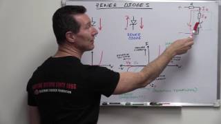


Zener is good for powering low power lasers at constant I and U,and also for providing constatnt voltage to the gate of MOSFETs and FETs in general
I use Zener diodes in combination with general purpose diodes with their anodes commoned together to protect MOSFETs from positive and negative voltage spikes. These are handy when application specific TVS diodes don't have the withstand voltages that I need. This diode buddy circuit will start to conduct if the gate-source voltage rises above, say 15V, and the general purpose diode will block source voltages from flowing into a gate that is off.
It's always a good idea to have your zener voltage above your working voltage, but low enough from your absolute maximum voltage rating. If your 3.3V chip has a maximum voltage of 5.1V, a 5.1V or even 4.9V zener wouldn't protect it from transients, because the knee of the I-V curve wouldn't reach a low enough dynamic impedance to actually clamp the voltage before it hit the ceiling limit of your chip's maximum ratings.
Used heavy stud zener to set bias voltage in 572b amp. Worked well.
Well nearly all of those linear regulators you mention use an internal zener reference.
I use zener almost exclusively as a protection device on the input of the circuit. For getting a regulated voltage i usually use a buck or bust or buck/bust converter and add sufficient decoupling to the ic's or if the circuit is very sensitive to ripple i use a linear power regulator.
I used the combination zener and resistor to feed one input of an opamp with a stable voltage (let’s say about 5v) independent from the supply voltage (a 12 volt car battery for example). Than using a potentiometer as a voltage devider on the other opamp input you can set a threshold at which battery voltage the opamp turns on or off (thus depending on which input of the opamp is connected to the higher of both voltages of course). With this I created a battery low voltage monitor that switches of a relay (could also use a mosfet) that kills the power to the circuit if the battery went too low.
as noted, Zener diodes were at one point a popular kind of regulator for (particularly British) motorcycles. The 70's Norton Commando (an otherwise really neat bike) in particular frequently demonstrated your point as to why this was a bad approach, burning out bulbs and leaving dead motorcycles on the side of the road and riders walking wondering why they thought buying this bike was a great idea. (Don't ask me how I know). They were Lucas systems so perhaps this wasn't really that surprising.
I've used a zener as a reference to the base of a PNP power transistor (with a limiting resistor across the collector to base) to brute force regulate incoming voltage. The output was taken from the emitter and could be further smoothed by a low capacitance of a few microfarads. It worked well enough when the 78xx series was a bit more pricey.
Same here: resistor and zener as a reference for a emitter-follower PNP transistor.
Night Stranger same. I did this for one of my electronics projects as an undergrad.
Had a flashback there. The condo where I lived at the time had some issues with heating and cooling. I was a pretty decent pixie wrangler so I took off the cover and was intending to look for any obvious damage to the board. I nearly screamed in horror at what I found. The board had 24v AC coming in that went through a single diode and then through a voltage divider to power the rest of the board. It had big resistors and the board was even cut out around them so they knew how hot it would get. The board was discolored around the resistors from the heat. I can't remember the exact board but it was an older Honeywell. On top of it all that cheaply made, single sided board was $600.
+cypherf0x yikes! It amazes me that a brand new HVAC unit today still has a control board with mostly through-hole parts.
I use them as they're intended to use: as a voltage reference for opamp or everything else with practical no load.
Voltage dividers using resistors were common in valve equipment where a lower rail might be needed for something. But because those circuits run at high voltage and are high impedance it's more practical. The voltage output of a divider will remain quite constant if the bleed current through it exceeds the demanded load current a factor of 10 or so. That will work, but naturally is highly inefficient.
You could improve it by using higher value resistors and then use an emitter follower to source the load, but by the time you muck around with that you might as well just get a three pin reg. And of course the divider/follower doesn't have any line regulation (for that matter ANY real regulation) at all. That might not matter though if the feed to it is already well regulated, such as your 5 volt USB rail.
Zener diodes provide a better voltage reference source if the current through them is kept constant. There are quite a few circuits that can do that, but a simple way to achieve a quasi-constant current is to replace the fixed resistance with a small incandescent light bulb, the voltage & wattage found experimentally to approximate the value of the resistor or current flow you might have calculated to begin with when the bulb has a bit of a glim to it.
If you want a quick and dirty way to knock a voltage source down by a couple of volts just use a string of two or three normal rectifier diodes in series with the supply & the load. That was always a good trick to run 5 volt TTL logic from a six volt lantern battery.
Nice job, I like your videos, the only ckt that comes to mind right now that I would use a Zener to set a voltage would be the old crow bar protection ckt. Thanks for sharing and keep up the great work.
Zener regulators are used in tandem with the similarly kludgey CR dropper ac/dc supply design when low power loads are plugged into mains.
In many cases zeners work well as voltage references. Also, if the next stage is very high impedance, then a zener, or for that matter, a voltage divider, works fine.
I use Zeners all the time when I need a stable interlocking sympical adjusticator. Works very well.
One of the most required videos!
This circuit can be improved significantly by adding an NPN BJT. Connect the collector to the 5v line, the base to the zener cathode, and the load between the emitter and ground. The emitter voltage will be about 650mV lower than the base voltage but this can be compensated for by adding a regular forward biased diode in series with the zener diode. You'll be able to use a higher value for R1 and your voltage regulator won't be consuming much idle current.
I’ve used them for my senior design project. We created a hand crank generator using 50w plate mounted zener diodes to output 5, 9, 12, and 15V at 0.5A. It worked like a charm.
voltage reference diodes are neat and similar, but not intended to supply very much current at all.
I use zener for high impedance load like op-amp input clamp, feedback regulator etc. only. Thermal drift is a problem too even in a light load
I have used zener diodes for bias on a tube amplifier.
Obviously zener diodes are used in voltage regulators but they are also used as a voltage reference in tuning circuits using varactor diodes to tune the frequency.
I have used zener regulators on many occasions, generally when I don't have a regulator on-hand. I have been trying to design a simple but good lab bench power supply (dual-rail 0-30V, 0-5A), I would test my circuit with a small 12v 50va transformer, and to get a stable +- 12V for the op amps, I used a zener regulator, since I had no linear regulators on-hand and a whole bunch of 12V zeners and big resistors. They are also generally more-used as voltage references, although in honestly they make voltage reference ICs which can be used as drop-in replacements for zener references and offer FAR better "zener impedance" and much more accurate and precise voltages.
Also I used one in my tesla coil video because 50V killed my (only) 7812 in the video! I left it in as a bit of comedy! :) I continued the video with a shitty 12V zener shunt regulator.
i have used a zener parallel to the output of a 7805 regulator, but i guess it was just to confort myself, so far it's been working
i used it IN a voltage regulator that was basically a zener, opamp, and BJT with a few jellybean parts thrown in but never used it on its own as a regulator.
It makes sense for use in signal regulations and protection. At least I it's the way how I use this circuit You showed. :)
I got a nifty battery eliminator circuit for my VTVM that uses a zener diode.
I attend to use zener diodes as voltage references for opamps.
I currently trying to fix some powered studio monitors (Roland DS30A, 30 watt version of the DS90 studio montirs which one can find the schematic on the net) and they use a transformer that gives about 25 volts, into a voltage divider, using both (they call it 29 v on the schematic but it is RMS so when it gets rectified it is 25 v) they have mirror circuits after the bridge rectifier, where they supply +25vdc and -25vdc, as well as after the divider, because if two 15 v zener diodes they also supply +15vdc and -15vdc.
In troubleshooting it was driving me crazy. I was getting a very low (around -5.8 vdc) voltage at what should be -15vdc power out to the board.
I even took out the zener, breadboarded (three nine v batteries in series, for about 18 v) and tested the zener and it seemed to be giving -15v. But after changing out some caps, etc. kept coming back to it, and traded it out and voila…-15v.
But the thing is, it is powering a LM4766 Audio chip, and I’m assuming that chip is varying very much in its current demand as it lowers the actual speakers.
Now I’m thinking this is a pretty bad design. Still am not getting sound. Was thinking it was the mute section, and something seems wrong there, though I replaced the LM7466 chip, used thermal paste (has a HUGE heat sink). Blew up a few also, not sure why.
I have been look into this these days,but I didnt heard that option before.Thanks for sharing,Using an esp8266 with 50 hz 230v city electricity via phone charger and lineer regulator might be an option,at least it looks alike.
I've used a zener as overvoltage protection in a photovoltaic trickle charger. Tiny circuits for tiny solar cells and tiny batteries.
Zener regulators are only good for voltage references and protection circuits.
Zener, to power a bunch of LED's under vacuum tubes for cool lighting effect in a vacuum tube radio, when pulling the power from the filament circuit.
Technically speaking you could use resistors. For example if you use one that let 10x more current flows in it than what your load could use then you get 10% voltage regulation. Of course for significant loads it means huge wasted current and a lot of heat. Also as you said if the input voltage changes the output changes too. Conclusion: you can but only for very small loads and if the input is stable. This is exactly what you do when you use a voltage divider to send a signal to an op amp, a adc....
I have used Zener for limiting voltage from Arduino 5v to some chip that had 3V3 logic.
I use LM431 every time when I need voltage regulator under 100 mA. Cuz it's easy and on my work we have have a huge rail full of LM431)))
What's the difference to an TL431? Also can sink 100mA and is what I use (mostly as reference for opamps though). You can get 50pcs of them for less than 2$.
Same same.
duckduckgo.com/?q=TL431+versus+LM431&ia=web
Just discovered your channel and subbed it instantly! great work!! i hope to learn more from u :)
Amazing explanations!
I used zener dividers output conected to tip122 as an emiter repeater. 7812 could not handle the 60 volt input, so i mande my own LDO from 3 components.
Excellent !! :)
Good video brother
Well said, thank you!
Just found your channel and subscribed.
Honestly I think I'd never use this setup for regulating voltage unless, like you said if it's a stable load. I have a few voltage regulators lying around anyways. I'm studying electrical engineering, but I won't take my circuits class until next year so in the meantime I'm getting a minor in computer science.
Is the best way to protect against reverse polarity in a circuit to use a mosfet on the ground to the battery on a DC system?
You mentioned your forum, but no link in the description?
I had to google the forum?
+Josh Kaufman it was in the video, discuss.addohms.com.
Zeners can be a decent alternative for a cheap voltage reference.
Power amplifiers with DC servo use Zener diodes to bring down the supply rails to +/-15V.
Neither the voltage or application sound right. Seems like the zener is being used for over voltage clamping.
DC servo in a power amplifier is usually a simple opamp integrator. Since you don't need super stable supply to the opamp and most of the times the opamp is FET input the current draw is very small. A zener is perfect for this situation unless you have a dedicated low voltage power supply just for that opamp.
I use it on Attiny85 AVR controller!
Run without any parts it fine~
But When I add LED on Attiny85~
Project etc worse ... LOL
And .... Thanks your video
It makes me know more about zener diode !! XD
I will try to use linear Regulators on my next project!
Thanks, great video!!
Great video thank you.
Thank you
making a voltage divider to decieve an ecms DC voltage input from the O2 sensor, what recommended resister/ diode type y'all think would
be best ?
Thank you so much! know I know why using voltage dividers as Vcc for a bluetooth module is not a good idea!
would a capacitance voltage divider suffer from a similar problem?
When simulating this in LTSPICE it seems to be a very bad idea for DC. For AC it would work better but then also the load will have a massive influence on the divider.
In radio circuits, everyone agreed to use 50 ohm or 75 ohm impedances as loads. So in RF, you have a constant load. This allows you at high frequency to use passive components to create voltage dividers. In RF those passives tend to be inductors and capacitors since they're lossless. (btw in AC circuits you can raise and lower the voltage with a inductive or capacitive deviders)
Something freaky about RF voltage dividers is that if the load impedance (50ohms) is equal to the transmission line impedance, than the effective impedance is just 50 ohms. In most cases the transmission line impedance is not 50 ohm. So we use impedance matching circuits which tend have a voltage division topology.
+lol212ist Yes. But in general you wouldn’t use one. They aren’t usable at DC. At AC it is more common to use a transformer for isolation/safety.
I don’t even remember building one back in school.
Is there an advantage (or disadvantage) to using a buck converter and then a linear voltage regulator for a big voltage difference between input and output or high current? The L7805 gets really hot and I was wondering if the buck converter could mitigate that and the voltage regulator could smooth the output.
The technique you describe is used in some audio or sensitive data acquisition systems.
AddOhms Wow awesome! Thanks for the reply!
I'm trying to do this at the moment, I'm trying to make a portable CD player out of a CD drive from a hifi, I'm using an 18v drill battery, I need 12v and 5v for the drive, I'm messing about with resistors and zeners to try and tame the voltage haha, I'm learning a little bit I suppose
You need regulators. The motor should be a buck style and the 5v could be either a buck or linear.
Aren't voltage dividers also used to create voltage references in opamps (for example)? Isn't there some other catch to create references?
They are very useful for references.
You answered a lingering question of mine with this topic.
I would like to ask.. how can a sg3525 or tl494 be powered directly from the mains (220vac)? I'm trying to build an smps (220vac to 24vdc) and these are the chips available to me.
The resistor divider is ruled out , I can see.
Would the zener combo work?
Would really appreciate your reply.
"Little knowledge is a dangerous thing."
Well said @Piratekitty.
I've tasted a little knowledge, got myself in danger and I'm decided now to keep gulping.
I'm very aware I can order cheap smps units online but understanding for me is doing not only watching videos or reading books.
Shifting the conversation a little to current regulation: I just got an RPi 3B and added an audio hat. I am using a wall-wart USB charger that is rated 2A nominal, and the power LED is staying steady on. According to Pi getting started info pages, for the 3B that means power supply adequate for that config e.g. it would start to flicker if current starved. (They say that the meaning of the power LED in the 3B (all Pi3s?) is opposite of earlier Pi b boards.)
Sooner or later I'm going to want to add some more gadgets, thus will incur more current draw. The recommended 2.5 A wall wart would be an option, but circuit tinkering begs the larger question: how much current can be safely sourced through the preferred micro USB connector? I have a few good computer PSs with multi-amp 5V leads but hesitate to try them for fear of frying the 3B. I have other smaller 5V power supplies scavenged from junk electronics from hamfests and transfer station discards. Seems a shame to buy something when I have all this good inventory to work with.
So I'm confused about how to think about current regulation, and about folklore wisdom that says devices will only draw the current they need, even when the source supply is well in excess of their needs. Clearly the LED with limiting resistor circuit is an example of folklore being wrong in some cases. I'm reasoning that to be absolutely safe I need a current limiting circuit between any high current 5VDC source and the Pi micro USB. Maybe you could work that into a video, or point me to a tutorial that addresses my question? Also, would you weigh in on back feeding Pi through any of the USB ports < seems risky to me. tnx in advance.
You've made some incorrect assumptions which make answer these questions difficult. I've posted a full reply here. I don't mean to pick apart your question, but I felt the need to break it down to address each of the points. discuss.addohms.com/t/current-regulation/673
tnx, my comments at the discuss forum. Note that the Pi3B+ has PS redesign. details and schematic at Adafruit site.
I can't find anything on a "Pi3B+".
The Pi 3B is the latest. The "B+" is the final revision of the *original* Pi. This "redesigned power supply" is just a change from linear to switching supplies, introduced with the B+. For reference, I did a video introducing the B+ when it came out: ua-cam.com/users/edit?o=U&video_id=8ua7dkTLGII
There are no official schematics for any of the Pi, anywhere. The Raspberry Pi Foundation does NOT provide complete schematics. The most they offer are diagrams showing the I/O connectors. Which, aren't even complete.
(Slight edits. I confused the 2 and B+.)
a question, I have an analog output 0~10 volt but microcontrollers for measuring analog input just accept 0 to 5 volt how I can use voltage divider now?
That is a typical purpose for using a voltage divider.
@@AddOhms Can I use zener diode to break the voltage to 50-100 times. For example, 1 kV input and viewing 20 V in an osciliscope (using Zener)
I'm a little confused about the definition of 'active load'. The Wikipedia article made it sound like it was some sort of diagnostic doohicky. Can anyone clarify?
Load is the device being powered. "Active" load means it can change its power usage on its own. Like a microprocessor. A non-active load, or "passive' load is like a resistive heating element. It, basically, presents a (nearly) constant load to the circuit.
So I have a DC fan with an operating voltage of 3.3 to 5v and draws 120mA that I'm powering via USB. I'd like to it to run it at 3.3v to make it quieter so I'm thinking a simple resistive voltage divider circuit would work fine in this case?
You wouldn't use a voltage divider. A series resistor will probably work.
Hello. I want to convert a battery powered kitchen clock (uses one 1.5V AA) to connect to mains power. I was thinking of using a USB charger (outputs 5V) and then changing the 5V to 1.5V. For this simple scenario would you recommend a voltage divider or a regulator? Thanks.
If it is one of those motor driven types, then maybe. An issue you’ll likely run into though is that many USB chargers are switching supplies and have a minimum current required for regulation. Especially cheap ones. That tiny motor may not draw enough.
The upside to use a voltage divider, however, is that you can probably set the resistor values to bring it into regulation. (You could with a regulator as well.)
So. Make sure you do some measurements.
use shunt regulator or series regulator circuit instead of LM voltage regulator if you have not one.
0:13 Not as a regulator, but of course you can use a voltage divider to power an esp (assuming you have a steady input voltage of 5V), you just need one 2 ohm resistor, one 1 ohm resistor (both resistors should be rated at least around 5 W) and 5V at about 2A and you're all set (you could probably get away with higher value resistors, especially if you have a capacitor to even out the ESPs current consumption). It's not particular reasonable if efficiency is anything you care about (although linear regulators aren't particularly efficient either unless you compare them to a voltage divider of course), but it's certainly most possible.
Thanks, I guess ill have to use Voltage Regulator
More like this!
What about using a zener as a voltage reference feeding the inverting input of an op amp used as a comparator?
That basically what a linear regulator does.
@@AddOhms So you could use an 8v zener OR an 78L08(or similar) if you wanted an 8v reference on the comparator? Is one better than the other or more appropriate?
The datasheet answers the question for you: “The L78L series used as Zener diode/resistor combination replacement, offers e improvement along with lower quiescent current and lower noise.”
@@AddOhms Oh ok, thanks. I am not an electrical engineer and I am trying to learn this on my own so reading data sheets is not very helpful. Understanding the information on data sheets should be a series of videos unto themselves.
So what's the ideal source for an active load? Fast solution is the voltage regulator fine, but if I had to design from scratch that would be a complex power source?
+Emiliano Barros I don’t know what a “complex power source” is. You would use a voltage regulator.
AddOhms sorry I meant complex in design since I don't know a lot of electronics. Alright, thank you so much for your knowledge!
+Emiliano Barros Watch my videos on Linear and Switching regulators.
how can i change the voltage from a 24V signal sensor to the 3.3 volts max of a ADC
Voltage divider
What if you use the 10k and 20k resistors as before, but you feed it into an op-amp buffer?
That’s just a basic op amp buffer at that point.
Could you please design a homemade high amperage and wattage circuit for mppt charge controller
I have never designed or built a MPPT. It isn't likely something I will cover.
I think diodes in series are good solution , I tried this before , its working
Ive never thought of doing that. lmao
I'm curious though, how can one calculate the current consumption of a device? Should I just add current consumption of each element of a device? But in that case, how to deal with basic components such as resistors and capacitors?
"Basic" components adhere to Ohm's Law. Active devices, you have to design based on the information in the datasheet.
AddOhms and how about the whole device circuit? E.g. if I design a simple power supply with LM7805 (which is an active devicw, as I understand) and couple of resistors/transistors/capacitors - do I just calculate the current consumed by each element and then just add all the numbers alltogether? Or there are some formulae/laws/theorems for that?
Now you are just describing basic circuit analysis.
Utiliser un amplificateur en suiveur pour l'adaptation d'impédance
I prefer op amps, but an emitter follower would work too.
I love to work free for you for 6 mths in return you can teach me more about electronics
+Bill Queensland I’m flattered. Thanks. But not something I can do. My day job takes up most of my time.
If you can read, buy a good book like; "The art of electronics". Its not cheap, but worth its weight in gold and considered the bible of electronics self study.
When you're finished, you can teach AddOhms a trick or two instead.
Lol..I doubt that.His too smart to learn anything from me.Even if i read all the books in the world.His got the gift when it comes to electronics.
Youre my fav on here.You explain things well and i learnt from you over the years.
PirateKitty . It's not that expensive maybe $100 bucks or so. Cheaper than a 101 EE course. It also gives a more complete picture than a 10 min. video can. Avoid the counterfeit ones they aren't the latest printing of the 3rd edition which has the most errors corrected.
@1:31 Why use a 10k-ohm & 20k-ohm and not 28.3-ohm & 56.6-ohm pair? The current divider ratio is still 2/3 of 5V, giving you 3.3V. Since we want Vout to be at 3.3V, the voltage drop across R1 should be 1.7V and since we want 60 mA of current flowing, 1.7V/60mA = 28.3-ohm.
I suppose it's because it's difficult to find resistors with those values and like you said -- the voltage output isn't stable because the device does not always draw 60 mA. If it drew less than 60 mA, say 30 mA, then the voltage drop across R1 would be .85V and Vout would be 5V - .85V = 4.15V. Uh oh. I see now.
What if you are trying to simulate the voltage and natural voltage drop off a battery (ex. AA battery) and a stable linear voltage isn't really required? Are plain resistors ok then?
In that case you aren't building a divider or a regulator.
Resistors are linear devices. The voltage falloff from a battery isn't linear. So I don't see how you could properly simulate one with just a resistor.
A zener cant handle higher current
I have seen zeners in circuits just to provide 5v to a ic just watch big clive the chinese love them lol in cheap gadgets.
Ok,but If You are working whith a hi voltage in The input And You want regulate It to 15v output
Lets say 90 volts imput.
No. That is even worse. It would burn enormous amount of power even at low currents. A switching regulator would make more sense.
U are wrong . . Your concepts about zener are not Clear
+zulqarnain najar Good feedback. Thanks.